I have tried by several minutes and i could not understand the circuit.... say... the operation....it receives the feedback by the red line you see at down rigth side...and them,we have the series of diodes in conduction to the down left side....how this works?
Can you describe this in details to me, please, as i could not understood by myself, and, in a genuine humble way...asking for help.
Of course, i believe that, if decided to use hours i will have the chance to realise, to conclude the operation... also i can simulate and the software will show me how this operates..but takes too long time, and maybe someone can explain this in a matter of minutes... when i will loose hours.
I have not this time , as i am beeing very busy those last weeks, and despite busy, that thing continues buzzing inside my three neuronius rusted and eroded by the time.
I hope the "Walking audio enciclopedias" we have, come to help, unfortunatelly i have not too much hope about that, as when we really need, they do not use to appear.... they prefer obvious questions only... with exceptions... are you one exception?
The reason of this question, more then curiosity, is based into several criticism i use to read and listen about this circuit...people say they kill sonics, but no one was able to explain why?.... how kill sonics?... compressing?... cutting peaks?.... limiting?... acting as an AGC?...well...how it works.
NAD 3220, and some clones, and you can see a small part of the schematic i will post down here, are considered excelent sound reproducing jigs, considering the low price when first sold.... thousands folks use them as reference...the price jumped very high those last years in my place... and cannot find them paying less than 1000 dollares in my country... and... if you manage to find someone really stupid that wants to sell it....as those units are famous, something considered very good around the world.
I could never listen the unit...but will build it entirelly by the NAD schematic to evaluate by myself, not needing anymore to believe into Magazine Reviews...but, in advance, would be happy to understand how this circuit operates, and why everybody use to tell us to keep this "ACC" switch off.
Thank you in advance by the kindness to explain how the circuit operates... step by step please... a description please.
The image may be from a Proton 520...but i am not absolutelly sure, because do not know exactly if we can post commercial schematics here... so... i am informing, in advance, beeing carefull, i have found this schematic part somewhere in the web.
I think Planet 10 have those units, or at least he had....he has special listening skills, because speakers, and this kind of excelent units may be something he may like.
regards,
Carlos
Attachments
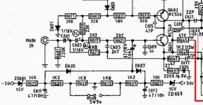
The red line is feedback - it has no direct effect on the input limiter function.
When the switch is off the input voltage is divided by
R621 over R629+R633 (negative input signal) or
R621 over R631+635 (positive input voltage).
That is - when the input signal level is over the diodes treshold voltage. ( It does not say what type but I guess silicium)
When the switch is on the input voltage is divided by
R621 over R629(negative input signal) or
R621 over R631(positive input voltage)
....when the input signal level is over the diodes treshold voltage.
So if the switch is in 'on', input voltage peaks over 0.65 V is divided harder, making it a limiter.
I think NAD puts the diode limiter in the feedback network.
You can see some NADschematics here:
http://www.audio-circuit.dk/
Edit:
...unfortunately none of these schematics seems to be the NAD models with Power Envelope - NADs marketing name for the limiter.
Good!.... excelent description, a real master you are
Absolutelly no doubts about.
The ACD site, by Doctor Jan Dupont is excelent, and i use it very often..he is the best into boards production into the entire forum...well...this is my point of view...no one better than Jan
Boys.... if you wanna to go deep into this subject, take you seat and go ahead..... i am very satisfied with the answer, not needing more informations..... wanna continue folks?.. this is up to you.
regards,
Carlos
...unfortunately none of these schematics seems to be the NAD models with Power Envelope - NADs marketing name for the limiter.
Look for models with PE, like 3240PE or something.
Look for models with PE, like 3240PE or something.
I have many NAD models that are not included into ACD schematic list
But i had informations he already has many other schematics and will upgrade his site very soon, as he did last month.
I have the needed ones, including all versions of the 3220 model, and some of NAD models are repeated into ACD site.
regards,
Carlos
But i had informations he already has many other schematics and will upgrade his site very soon, as he did last month.
I have the needed ones, including all versions of the 3220 model, and some of NAD models are repeated into ACD site.
regards,
Carlos
It’s all about controlling the DC voltage potential at the diodes anode or cathode (depending on polarity). After Zeners the voltage from the 34V supply has dropped to about 19V. Then there is a voltage divider formed by the 10K, 1K2 and 1K8 resistors in series. (There's a circuit for both halfwaves of the signal). When switch is open the resistive divider sets a voltage potential of about 4.3V to the node that interconnects 10K and 1K2 resistors. The signal clips when it exceeds this voltage and the forward voltage of the diode. The capacitor acts as a shunt for AC signals. When the switch is closed the opposite DC voltages cancel each other and form a virtual ground at the node where 1K2 and 1K8 resistors interconnect. This affects the voltage divider and the voltage potential at the node that interconnects 10K and 1K2 resistors now becomes only about 2 volts. This means that the signal voltage required for clipping becomes lower.
Excelent description Doctor Temuk.... another master
This have clarified once more the basic operation of this circuit...and confirm last informations including more details.
thank you...both of you.
regards,
Carlos
This have clarified once more the basic operation of this circuit...and confirm last informations including more details.
thank you...both of you.
regards,
Carlos
But i had informations he already has many other schematics and will upgrade his site very soon, as he did last month.
Carlos 😉
Thanks for the kind words. And yes I update the schematic/service manual collection constantly.....
Within the next week further app. 82 schematics/service manuals will be added, however sadly none with NAD PE circuit 🙁
If someone got one or more of these, please email them to me 😉
I have some of them Jan, I've found them yesterday
and will upload to you.... and matched my spectations... Planet 10 have published 2 schematics in our forum some years ago.
regards,
Carlos
and will upload to you.... and matched my spectations... Planet 10 have published 2 schematics in our forum some years ago.
regards,
Carlos
Look for models with PE, like 3240PE or something.
There's a combined service manual from 1989 for NAD 3020e and 3220PE at:
http://www.schematicsforfree.com/archive/dir/Audio/PRODUCTS/AMPLIFIERS-INTEGRATED
Haven't had a chance to get a good look yet but in it the limiter circuit is pretty much the same as the one posted in this thread.
ACD said:
Within the next week further app. 82 schematics/service manuals will be added, however sadly none with NAD PE circuit 🙁
If someone got one or more of these, please email them to me 😉
I've just did😉
Thank you Temuk, i have just downloaded and will sent to ACD
Good Aparatusonics..... good.
regards,
Carlos
Good Aparatusonics..... good.
regards,
Carlos

Do it slowly.... along those three next monthes
If someone need some of those schematics, we can provide them, uploading or providing some links to them.
Relax Mr. Dupont, you have already contributed a lot to our communitty.... we can wait.
regards
Carlos
If someone need some of those schematics, we can provide them, uploading or providing some links to them.
Relax Mr. Dupont, you have already contributed a lot to our communitty.... we can wait.
regards
Carlos
- Status
- Not open for further replies.
- Home
- Amplifiers
- Solid State
- Clipping control... ACC... NAD 3220 feature, can you explain how this operates?