LEDs (being non-linear), don't you think you are introducing (a) distortion (contribution) by adding LED in the screen network? Thanks.
Remembering that LED-LDR is "LED → light dependent resistor" (AKA photoresistor), it turns out not to take very much current to substantially lower the LDR's resistance. Below 1 ma.
As to the effect on the audio path, for the screen, remember that either you're using a “ultralinear” tap of the output transformer, OR, you're using a screen supply, which nominally should have a filtering reservoir capacitor strapped-to. Screen voltage ideally should be a near-constant. Not its current tho!
So, having a very modest total-current sensitive LED in series between the screen pin and the screen supply has 2 benefits - unidirectional (like the LED), and impact-modest. If the nominal clipping point is above say 7.5 ma, and the LED has a bandgap of 1.5 volts (say… you need to look up), and you want it triggered over 7.5 ma, then (E = IR, R = E/I = 1.5 V ÷ 7.5 ma) → 200 Ω will do it. I'll trigger. Moreover, it serves to lower effective impedance of the 200 Ω ballast resistor during peaks, increasing linearity thru its presence in louder passages.
Just saying.
GoatGuy
Last edited:
Originally I just wanted to build a circuit that would light an LED when the grid came within 0.5V of the cathode to indicate driving the grid positive, but now I'm thinking an output clip light might be nicer.Kodabmx,
Do you want to indicate Clipping at the amp output?
What is the topology of the amp that you wish to measure clipping?
For certain kinds of amplifier topologies, and for certain loads, it can be more complex than what has already been discussed.
It's a push pull TRIODE connected KT120 amp.
Last edited:
Thanks Goat guy.
What I was referring to is that the LED does not conduct current for a voltage at 0.1V or even 0.6V or more. So during that low voltage difference nothing happens.
I understand at higher voltage, the impact of the LED is probably negligible.
What I was thinking is most decent fixed bias amp has already a screen resistor, usually around 100R. Maybe using that existing resistor would be a elegant solution.
It is. Just remember (in this case) to choose a LED type that (1) isn't harmed by substantial over-nominal current, and (2) has a bandgap potential (“color voltage!”) that meets your needs.Maybe using that existing resistor would be a elegant solution.
For instance, for a 100 Ω resistor:
RED (older) LED = 1.8 volts … light-up at 18 mA.
YELLOW (older) LED = 2.1 volts … 21 mA.
BLUE (newer) LED = 3.3 volts … 33 mA.
RED (newest) LED = 2.3 volts … 23 mA.
Using E = IR → I = E/R … 3.3 V ÷ 100 Ω ≡ 3300 mV ÷ 100 Ω → 33 mA.
like that little trick? I use it all the time in calculations-by-hand. Tack on zeros to go to mA or mV or kΩ directly. Have to be nimble!
GoatGuy
Yep. Thanks.
I never thought at using the screen resistor as a way to indicate the tube's utilization.
I never thought at using the screen resistor as a way to indicate the tube's utilization.
I'll let George and Wavebourn debate whether video or sweep tubes are better for audio. Both are extremes, high gain or high current, and not what we usually do for audio.
If you want "a clip indicator", define what you want. Pre-clip? Already clipping?
I do have to wonder: if you won't hear clipping, should you be using a large amplifier around costly loudspeakers?
Pre-clip is just a peak detector to a level detector set to about 70% of nominal maximum voltage. If this is blinking at all, you are likely so close to clipping you may as well assume you are clipping.
This will fail when the amplifier is mis-loaded. A 1r load on a 8r tap, the amp can't make 70% of nominal voltage.
The next step is like the early Crown IOC. Monitor the NFB point. When linear this is zero (to the other input). "Zero" may run many mV due to internal distortion and phase shift. If it is higher, the NFB has failed, probably due to clipping.
Both schemes normally need a blip-stretching monostable so your eye has time to see brief clips.
The rise in G2 current VS plate voltage has a "knee" which is tube dependent. . . . . . .
I'm sure I'm proving my absolute ignorance of Pentode operating characteristics, but reading your post I wondered, Could it work to put a current source on the screen grid? - Perhaps feeding a constant voltage source?
Could it work to put a current source on the screen grid?
A current source set to a current that is above the normal operating point of the tube can be used to protect the screen grid from meltdown when the amp is repeatedly overdriven. It will normally be saturated and thus presenting a small voltage drop. Monitoring the drop across the CCS can be an indicator of clipping on some tubes.
This will fail when the amplifier is mis-loaded. A 1r load on a 8r tap, the amp can't make 70% of nominal voltage.
Amp clipping happens when the amp runs out of voltage headroom, or can not source the required current to force the desired voltage across the load impedance no matter how hard the feedback system tries to correct it. These are different phenomenon (which sound different) and require different means of detection.
An "8 ohm" speaker system is rarely 8 ohms. The impedance VS frequency graph furnished by the speaker manufacturer is only valid at low levels with a single frequency sine wave applied. Real music can make a speaker look like almost anything from a short to a high impedance (100 ohms or so) with an inductor or capacitor in parallel.
Overcurrent limiting or clipping may also occur due to magnetic saturation in the OPT, or OPT / speaker combination. This can often occur due to a high voltage condition caused by a speaker near resonance. A guitar speaker often has it's resonant frequency inside the guitar's operating frequency range, and often sits in an open back cabinet (undamped). This can cause saturation in the OPT.
An amplifier may behave in a predictable way into a load resistor yet do all sorts of unusual tricks into a speaker. Stick a scope across a speaker and watch it sometimes. I can routinely demonstrate 40 to 50 volt peak to peak unclipped bass transients across my "8 ohm" Yamaha NS-10M speakers from a single KT88 in SE. This does not mean that a KT88 is delivering 30 to 40 watts.....it means that my speakers are not 8 ohms in the bass region and there is no feedback in the amp to reign in the voltage.
The sensor in the screen circuit can detect an overcurrent condition in some tubes. A small unbypassed resistor in the cathode circuits may be a better current detector. A voltage across the load, or the plate circuit, type detector may be an indicator of voltage headroom loss, but neither can detect all types of clipping, and both are capable of false positives due to the reactive nature of the load.
In many cases an amp may clip visibly on the scope, yet the clipping may not be heard. Again this is dur to the reactive nature of the speaker and usually occurs nears the woofer's resonant frequency.
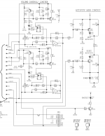
This circuit was the basis of my interest, but to try and simplify it and adapt it to the KT120 triode connected amp in question. It's from the schematic for my Yorkville AP1200.
The clip light indicated clipping before you hear any. OTOH hearing a 1W amp clipping is easy, hearing a 300W amp clipping is harder. Much like 10% THD is horrible in a 1W amp, but you probably wouldn't notice it at 100W (in a 12'x18' room).
The clip light indicated clipping before you hear any. OTOH hearing a 1W amp clipping is easy, hearing a 300W amp clipping is harder. Much like 10% THD is horrible in a 1W amp, but you probably wouldn't notice it at 100W (in a 12'x18' room).
Attachments
I made an output tube board once that had a mosfet follower that acted as a low-impedance supply for the screen. I added a BJT that would pull the gate of the mosfet down if the screen drew too much current, which was sensed across a series resistor. It would be workable to make some sort of series/parallel combination of resistors and an LED and make it so that an LED would light when the current-limiting feature was active during clipping.
As I recall, the circuit worked well but if you really pushed it hard (well beyond start of clipping), output would actually start to fall due to the sagging screen voltage and you would get little rounded "craters" in the tips of the waveforms, not all that deep but visible. Recovery of the circuit was instantaneous and those conditions would only be met if something was horribly mismatched so it didn't concern me too much.
If I had thought of the CCS-based current limiter mentioned above I might have tried that as well.
However, if I were doing clipping indication I would probably just split the input off to some opamp-based analog circuitry that would light an LED when input level exceeded a threshold. Not a true clipping indicator but useful to let you know that you are feeding a signal in that is bigger than the amp is designed for.
Very cool sounding circuit, SpreadSpectrum. It won't work for me though, I'm triode connected.
It wouldn't be hard to sample the plate voltage of an output tube and come up with something opamp-based that would light an LED if plate voltage hit a certain threshold. The problem is that you have to define "clipping" as a voltage and with a load that changes impedance with frequency you can't make that exact. The voltage of clipping changes with frequency because your load line is moving around with frequency.
That's why I would just sample the signal voltage at the input of the first amplifier stage and come up with a good ballpark estimate of where clipping will be, set a threshold and do some opamp magic to make an LED light up when a certain level of signal is reached (something with fast attack and slow decay so the eye doesn't miss clipping on transients). It may not indicate exact onset of clipping under all conditions but it will indicate that the tube amp is being driven really hard. I would consider that "good enough."
You could put a 1 Ohm or smaller resistor in the cathode circuit of the output tubes. Feed that current dependent voltage into a comparitor chip that drives an LED (current headroom exhausted).
Use a large valued resistor voltage divider to sample the plate voltage and divide it down to the level needed for another comparitor driving another LED( voltage headroom exhausted). Heep in mind that the voltage on the plate of an output tube approached twice the B+ voltage in normal operation. I have seen 4X peaks on an overdriven guitar amp into a speaker at resonance. The resistors must be rated for this voltage of a series string is needed.
This two pair circuit will not detect everything, and there will be some false positives, but it's the best "simple solution." It's safe to assume that if both lights are flashing, it's time to turn it down.
Another possibility is to feed the sampled voltages into a fast Arduino clone and play with some software to detect and mediate these events.
For a simplified version of Wavebourn's limiter, I wire the LDR optocoupler's LED across the screen resistor and wire the LDR across the grid to ground resistor in a simple cathode biased amp. When the screen starts really sucking current, the LDR shunts some of the drive to ground. This will not work when the driver is hefty (mosfet) or with a transistor or FET coupler, it must be an LRD (Vactrol or clone). As he stated a second Vactrol can be used to drive an indicator.
I have 10R resistors in the cathodes as sense resistors for the autobiasing module... Maybe I could use a triode to turn on a neon by connecting the grid of an output tube to the grid of the triode, and when it's biased near 0V the neon will light. Maybe a 6N2P cathode follower with the neon across the cathode resistor? My tetrode amp uses VR tubes for regulation, making a makeshift "drive" light on peaks.
Using my digital oscilloscope I watch recordings that have an electric guitar that is driven into clipping.
I can use no persistence, 1, 2, 5 second, and infinite persistence settings.
The current signal trace can be seen in the full field of already captured signal traces.
No, it is not my amp that is clipping, it is the guitar amp clippingin the CD recording; but it is also not clipping of the CD's full scale dynamic range.
That makes sense, especially with distorted electric guitar.
It's when you start hearing distorted piano that you know you're into "clipping". The funny thing is I've heard music that sounded perfectly fine with sinewave bassline and drums etc, but then a piano comes in and you hear just how clipped it is!
It's when you start hearing distorted piano that you know you're into "clipping". The funny thing is I've heard music that sounded perfectly fine with sinewave bassline and drums etc, but then a piano comes in and you hear just how clipped it is!
I'll let George and Wavebourn debate whether video or sweep tubes are better for audio. Both are extremes, high gain or high current, and not what we usually do for audio.
No need to debate. Lot of people who now lost interest in posting on this forum agree with us. What's the point in designing one more mediocre amp? Chinese comrades sell them cheap!
LDR itself does that.Both schemes normally need a blip-stretching monostable so your eye has time to see brief clips.
- Status
- Not open for further replies.
- Home
- Amplifiers
- Tubes / Valves
- Clip indicator