I am having some issues with designing an el34 amp.
I made a board using iec/ul 60950-1 creepage and clearance standards, but I have found that I cannot get the clearance that this standard wants in the actual tube socket.
An online Iec/ul 60950-1 clearance/ creepage calculator is found on WWW.CREEPAGE.COM Welcome!.
For 550V they suggest 3 mm ( 0.12 inch) at 2000 meters (6561 feet) altitude, for 5000 meters ( 16404 feet) I should multiply this by 1.48. This makes 4.44mm ( 0.18 inch).
I have +/- 2.7 mm ( 0.11 inch) between the lugs.
The tube socket I have is the Belton VT8-st.
Is this standard silly? Is there another rue of thumb that I can use for clearance caculations?
I cannot get the clearance that this standard wants in the actual tube socket.
Why are you designing a tube amp for use at 16000 ft altitude,
will you be marketing this amp to Tibetans?
Last edited:
"Creepage" is usually between the wall-power and the user. We want LARGE factor of safety when an arc-over might kill somebody.
An arc-over across a tube socket may kill a tube but not (typically) the human.
That creepage is not aimed at tube sockets.
The EL-34 has been criticized for over-optimistic voltage ratings (particularly the 800V limit). Recall that the first 6L6 had a 400V rating which was quickly walked-back to 360V due to insulation failures in the materials of the day.
You didn't ask: IMHO High-volt Power-amp sockets should NOT be on PCB. That's how all factory amps are made today. And we see many more problems than when we just nailed sockets to chassis and hand-wired them.
The standard is written for AC power where 100s of Amps is available and could cause arc flash explosion. You just can't get that kind of power past your power transformer and fuse.
You should also have a ridge between each pin, which increases the surface distance. Creepage does not apply to insulator thickness, just surface distance.
There may be a problem with tube circuits that are not terminated and become a fly-back voltage boost generator. This is why you will see diodes on the plates of power tubes to prevent the generation of large negative plate voltages (pin 3) that arc to the positive screen pin 4, or inside the tube.
Last edited:
Thank you rayma, PRR and steveu for your replies.
@rayma: There are actually a lot of places situated at high altitude. In China ( I am not from China though), you are actually required to design stuff to work at 5000 meters, otherwise you have to put a sticker on it saying it is only safe up to 2000 meters.
@PRR: Nice to see you here, I am also a member at diystompboxes. I am not using a tube socket on a pcb. My issue is with the clearance, not creepage. You are correct that the user is safe from arcing in the tube socket, but I was thinking I wanted to make this amp really dependable.
Do you think 2.7 mm ( 0.11 inch) clearance is enough for 550V?
@steveu: I was taught that creepage ( tracking issues) and clearance ( dielectric breakdown) are purely functions of voltage and not of current. Please elaborate if you think differenty about this. I am not concerned of creepage issues in the tube socket because they could use a high comparative tracing index material for the socket.
I could condense my post into one question:
Is 2.7mm ( 0.11 inch) clearance at 550V dependable?
Arc blast?
I also feel creepage is voltage not current.
Note that a 550V B+ will be peaks over 1050V on the plates. If the load falls off and you put big signal in, over 2000V.
If you are gonna play on a mountain in China, or here by the salt-air seacoast, LONG-term, there may be no perfectly safe spacing.
This partial IEC doc shows ~~2KV wants 1.6mm at high degrees of pollution. Page 2 seems to want e.g. 14mm "long term". This is not out of line with extrapolating what my power company puts on poles; they presently have the road choked while they put taller ceramics on "for better reliability".
https://www.schneider-electric.com/.../live/FAQS/177000/FA177275/en_US/FA177275.pdf
The practical man would be guided by what Big Companies have done on known-good amps. What's the small UK company made near-mil-spec amps in the 1970s?
Thank you very much PRR. I have been looking for what iec 60947 ( the one you found) means by "long term stress" but unfortunately I would have to buy it to read it ( 300 usd).
How can 550V B+ peak over 1050V on the plates though .. I thought it was DC-ish by then? A load falling off would be the speaker disconnecting for the 2000V?
Were you talking about Marshall as the "small company that made near-mil-spec amps in the 70's"?
I have a copy of a plexi board here and the design is VERY far off from following the iec standards mentioned, but they do seem to be quite dependable ( when you don't run them dimed).
Max99,
In a push pull amp, when the tube on one side cuts off it's anode lead can go to 2 x B+ from transformer action.
At 16,000 ft you have thermal (cooling) problems as well as voltage withstand problems. The thermal problems also manifest as reduced current carrying capacity in wires. (I design airborne equipment in the day job).
Use a separate socket, not PCB mount, for the output tubes. If at all worried about voltage breakdown you can take preventative actions like: add double layer of heatshrink to anode pin wire connections and then spray the rear of wired socket with high voltage PCB lacquer making sure you don't get the lacquer on the connection points inside the tube socket.
The high voltage laquer increases the breakdown voltage by a large factor, Usually as a "butt pluck"/"rule of thumb" we talk about 1,000V per mm as the dielectric breakdown of air (at or close to sea surface). The laquer tpically takes this up by a factor of 25 to 30
This one (for example) has a dielectric strength of 30kV/mm.
Clearcote Circuit Board Lacquer | Chemtools(R) Australia
I use a similar product on a photomultiplier tube base laser receiever in an aircraft, the power supply to the PM Tube is 2200V.
If PCB mounting output tube sockets I would definitely use the PCB lacquer
I would guess the small company from the 70's making stuff to near MIL-SPEC that PRR was referring to was HiWatt.
Cheers,
Ian
Last edited:
Yes, HiWatt.
Since a ~~500V amp implies an OT too big to screw to a PCB, and has its own well-insulated leads, and your labor is free, _I_ would be thinking instead of landing pin 3 in a PCB pad, whack a 1/4" hole around where pin 3 will be and solder the OT leads to the socket pins, clear of PCB stuff. I'd also knock a screwdriver round-round in the hole to clear debris which would be high-spots attracting arcs.
I'm less sure about shrink-tube here (but I don't do it as a day-job). The high dielectric constant of plastic (solids generally) means there will be little potential drop through the plastic, thus more drop through the reduced air gap. Such things get very critical on >20KV power line terminations.
Heatshrink tubing does have a limited voltage withstand BUT much better than air. Typically not less than 10kV/mm but tubing wall thickness will be a fraction of a mm.
That is why I said use 2 layers. One layer would probably do BUT heatshrink is cheap so put a second layer over the top of the first layer.
Make sure the solder of the OT wire to the socket pin is done with wire parallel to the pin surface so there are no pointy wire ends poking out to the side for arc launch points. The Heatshrink tube will add mechanical strength to this connection.
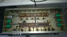
Hiwatt 400 Underside for your "edification"
Cheers,
Ian
That is why I said use 2 layers. One layer would probably do BUT heatshrink is cheap so put a second layer over the top of the first layer.
Make sure the solder of the OT wire to the socket pin is done with wire parallel to the pin surface so there are no pointy wire ends poking out to the side for arc launch points. The Heatshrink tube will add mechanical strength to this connection.
Hiwatt 400 Underside for your "edification"
Cheers,
Ian
Attachments
Last edited:
Thanks Gingertube and PRR.
Gingertube: which multiplier would you use for the 1000V/mm at sea level to convert it to 16000 feet altitude?
The insulating spray you suggested looks great, I have been looking at PlastiDip for this purpose because it looks more gooey, but I am still not sure if I need it.
PRR: thank you for your suggestions but the sockets are not on the PCB. Wouldn't the pins going to the pcb in your suggestion still have the clearance issues before they reach the pcb or wire directly soldered to it?
I thought about using a lower B+, maybe going to 435V, this would put the maximum voltage at the lug at around 1600V.
It is either this or the insulating spray/goo.
Max999,
You can judge multiplier by this article (from some Teledyne/Reynolds literature, they make the 5,000V rated, to 70,000 ft. High Voltage Connectors I use in the airborne equipment, sorry guys the connectors are way out of the price range that we can use for our git. amps, more than US$300 each, plus you would be asked to submit an end user statement before an order would be accepted, that is, they are subject to DoD export control).
http://catalog.teledynereynolds.com/Asset/1431.html
Most folk don't give this the consideration that you are, but get away with it.
That HiWatt 400 in the picture has 6 off KT88 along the back with B+ of just over 700V.
Cheers,
Ian
Last edited:
... to convert it to 16000 feet altitude?
Are you planning on playing guitar in aircraft without a pressurised cabin? 😕
There's a pile of amps out there with EL34s and too much B+. Yes, they're not MIL-STD reliable but they're mostly working
If you've got reason to be worried about arc over, get a tube with a top cap anode (e.g. 807)
Or pot your high quality socket (not vintage bakelite) and leads after soldering and double heatshrinking.
It's not rocket science (ok, it's sounding-balloon science)
Gingertube: Looking at the Pashen curves I see +/- 3KV per mm at sea level.
Is this derated to the 1KV rule of thumb per mm in real life because the 3KV is for spherical objects?
Thoglette: Yes a of of designs seem to work acceptabe although you can find several threads about arcing sockets and people complaining that "the board is conductive".
I am designing something and for that I would like to get some numbers about what is correct and what not. Thank you for your suggestions.
will you be marketing this amp to Tibetans?
Not surprisingly considering Tibet actually "belongs" to China 🙂In China ...., you are actually required to design stuff to work at 5000 meters,
Thanks Ian! Having a look under the skirt of a Hiwatt amplifier always is a pleasure to my eyes! That's the way how any tube amplifier should be built. But I'd rather twist the heater supply wires...
Best regards!
Best regards!
- Status
- Not open for further replies.
- Home
- Live Sound
- Instruments and Amps
- Clearance between lugs in tube socket too small?