The efficiency of a Class H amp can be further improved if the rails are varied directly by the SMPS rather than by a series pass transistor.
I kicked this idea around a while back Very Efficient Very Low Distortion Linear+ Amp and now have the time to finally implement it.
I am a little out of date with the latest ideas, does Bob's second edition discuss or analyse this?
Or is there a recent write up?
What I did notice is recent measurements of the Benchmark AHB amplifier that uses this technique and achieves the best distortion and noise I have seen from any class.
So some kind of Class H where the rails are modulated by the SMPS is clearly practical.
Most of the SMPS are built around a dedicated controller IC.
I need maximum rails around 75 V, minimum around 10 V and around 18 to 20 A peak for 600 W woofers.
Anyone know what the nicest chip is these days for this application?
Nicest is simple and low EMI.
For the switches I expect that the best choice will be a conventional silicon FET but am always keen to learn if there's any flashy new tech like SiC.
David
Turns out the Benchmark AHB uses a SMPS but doesn't use it to modulate the rails, that is done with a conventional linear circuit.
But they did consider SMPS controlled rails so it still looks possible.
Cuk has a buck converter that looks feasible on US patent US20110057640A1.
So the combination would be a SMPS with Cuk PFC and isolation from post #7.
Followed by the patent as buck converters.
Last edited:
The efficiency of a Class H amp can be further improved if the rails are varied directly by the SMPS rather than by a series pass transistor.
I kicked this idea around a while back and now have the time to finally implement it.
Hi, Dave!
Check LabGruppen FP10000q, already implemented as TD-class.
For the switches I expect that the best choice will be a conventional silicon FET but am always keen to learn if there's any flashy new tech like SiC.
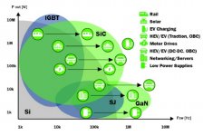
SiC at a side of higher voltage and higher power while there are better way to use GaN, something like TPH3208.
But really something like ipp320n20 will be good enough and a way better it terms of price and availability.
Use powerful driver like 1EDC60L12ah or 1EDC60H12ah they allow you to use up to 1,5 MHz base freq.

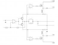
Also, is this a scheme you want to analyze:View attachment 859353
Use powerful driver like 1EDC60L12ah or 1EDC60H12ah they allow you to use up to 1,5 MHz base freq.
Also, is this a scheme you want to analyze:
Hi Pavel
There are some benefits to use a linear amp as the final output rather than a Class D.
A class D amp needs to switch fast to keep the distortion low.
Whereas I can exploit the speed of the linear section and use a lower frequency in the power supply.
The lower frequency allows lower switch losses, lower hysteresis loss in the inductor, and the skin effect is less so I can use thicker wire to reduce copper losses too.
So the trade-off now becomes about the size and cost of the inductive component.
I haven't done simulations/calculations but I expect maybe 200 to 400 kHz for the power supply would be reasonable.
Your nice chart shows silicon is still fine at that frequency, for reasonable power.
The second attachment has some problem, maybe it needs to be reposted?
Best wishes
David
Last edited:
There are some benefits to use a linear amp as the final output rather than a Class D.
A class D amp needs to switch fast to keep the distortion low.
Both have pro's and con's.
But, yes, anyway we go higher and jigher in terms of usable bandwidth.
In D class ams among other well-known things sound is affected by non-obvious param - deadtime. So yes, switch fast.
The lower frequency allows
Again, yes, but it becomes too near to be easily but properly filtered.
So, since there are already fast drivers and excellent Rdson*(gate charge) devices its becomes more attractive to use higher base freq.
The second attachment has some problem, maybe it needs to be reposted?
Sadly yes.

So, since there are already fast drivers and excellent...devices its becomes more attractive...
There are trade offs of course, and they are different for Class D and my proposal
There are certainly sufficiently fast drivers and devices but most losses do increase as the frequency is increased.
The extra losses are accepted in a Class D as trade for lower distortion.
In my case distortion shouldn't vary much with frequency so the optimum will presumably be lower frequency.
Must keep it sufficiently above 20 kHz to make it easy to filter and also to allow the power supply to react faster than the audio.
So that's why I picked 200 kHz to 400 kHz as plausible values.
I think the best way to keep the switcher noise low is to use a Zero Volt Switch circuit, this causes the frequency to vary with the load.
So the frequency is only an approximate place to start estimates anyway.
Sadly yes.
Ok, that worked this time.
It's not quite the scheme I had in mind.
If the power supply rail can be modulated by the SMPS then I don't need a separate low V rail and diode.
The core looks like a conventional Class B+ amp except each OPS rail is about 10V when the amp is quiescent and stays about 10 V above the output.
The down converter to do this will be run off around 85 V and output 10 to 75 V.
Some kind of Ćuk circuit looks well suited, with coupled inductors the output can be essentially free of ripple.
I think there is a ZVS variant that should have even lower EMI.
I want to find a suitable controller chip, will check AD first.
I hoped someone would make a recommendation to save me some time but this is more educational.😉
Best wishes
David
Last edited:
Not much interest but someone may find this in a search later so I may as well use it for my own notes.
Turns out the usual Ćuk converter is not well suited to the rail control application, RHP zeros limit the feedback speed.
So a Power Factor Correction front end followed by some kind of buck converter looks optimal for feedback optimisation .
Main problem is isolation, kind of scary to have non isolated power lines run around the amp.
But Dr Ćuk has a newer circuit that seems to solve the problem -
Single-Stage Isolated Bridgeless PFC Converter Achieves Over 98% Efficiency, 0.999 Power Factor | Power Electronics
Isolated, simpler, excellent efficiency and PFC, all at once.
Looks nice, so far anyway.
David
- Home
- Amplifiers
- Solid State
- Class H with SMPS