The amp don't care about there being different currents going to either channel just that the load is there.
If the amp used a post-filter (UCD-style) feedback, you'd be right, but as the Sure amp uses pre-filter feedback then leaving the output unloaded is perfectly ok, provided that you ground the audio input, so that the channel is not driving audio into an unloaded output filter.
Ouroboros, Thank you for your suggestion. When you say to ground the input, what exactly is the wiring for this?
Also, does anyone have any suggestions for a single channel class d amplifier I could use to replace this Sure amp with? The only mono Sure amp I see is 600 watts. I only need 50-100. Thanks again for everyone's advice!
Any update on how to do this? Reading the documentation it seems you can parallel the tripath based amps by jumping the config pin (24) to the vdd pins (21,22). Is that easy to do? Saturnus said you can join the inputs and parallel the outputs. Is there a difference to this methods?
Thanks!
Thanks!
Hi, sorry to resurrect an old thread. I have this TAS5630. Is joining the inputs and paralleling the outputs an option? Thanks!
As the TAS5630 is also available as a 600w mono, I assume the 300w stereo channels can be paralleled. Can anyone confirm I won't fry anything so long as I use a couple of 1/4w 100ohm resistors on each channel before combining the inputs?
As the TAS5630 is also available as a 600w mono, I assume the 300w stereo channels can be paralleled. Can anyone confirm I won't fry anything so long as I use a couple of 1/4w 100ohm resistors on each channel before combining the inputs?
600W mono means one input and one output. 300W stereo evidently means two inputs and two outputs. You can always connect the two inputs of a stereo amplifier and have "mono" in two separate speakers connected to each of the two outputs. What you cannot just do is connecting the two inputs to one and the two outputs to one without careful study of the design. PBTL is possible for TAS5630 such that at PCB level you can connect the chip as an amplifier with one input and one output.
Last edited:
600W mono means one input and one output. 300W stereo evidently means two inputs and two outputs. You can always connect the two inputs of a stereo amplifier and have "mono" in two separate speakers connected to each of the two outputs. What you cannot just do is connecting the two inputs to one and the two outputs to one without careful study of the design. PBTL is possible for TAS5630 such that at PCB level you can connect the chip as an amplifier with one input and one output.
OK, thank you and sorry for the noob questions. So if I understand correctly I can combine the signals into one input, ground the remaining input and then power one speaker from just one output, but to prevent damage I'd still need a dummy load on the other output?
What do I use as a dummy load? This won't affect power consumption as no audio is being driven through the channel in question?
Correct, you can use one channel only (300W) and leave the other idle. Yes as it is a class D chip, you have to connect a dummy load (8 Ohm/10W) to the output of the channel that is not used and short-circuit the corresponding input through 1K if you have. This, to avoid the idle channel picking up noise.
For the active channel, make a resistive summing with two 10K resistors and use that as input to the active channel.
The idle current consumption for the whole amplifier remains the same such that you can consider the half as wasted energy since you do not use one channel.
You can sometimes do tricks to combine two channels into one (mono) but that requires changes of the amplifier. My impression is that you would like to avoid that?
So short unused output with 8 Ohm/10W and short input with 1K (1/4 W ok?).
Input summed with two 10K resistors (guides I have read suggest 100 Ohm, why such a big difference?)
Idle current stays the same, but presumably when playing music power consumption is roughly half than if I were using two speakers? Therefore 8 Ohm/10W resistor is also sufficient and won't heat up etc. during amplifier's use?
Correct, I already feel out of my depth so would rather not start messing with the circuitry.
So short unused output with 8 Ohm/10W and short input with 1K (1/4 W ok?).
Correct, and 1/4W OK.
Input summed with two 10K resistors (guides I have read suggest 100 Ohm, why such a big difference?)
It is a balance of loading of the source. Output impedance of the source will be the two resistors in parallel (5K or 50R).
The differential impedance between the two source channels will be the sum of the resistors (20K or 200R). Differences in the signals on the two channels will be loaded with only 200 Ohm which in my view is too little.
You may also use 4K7 instead but 100R is too little unless you have a very low input impedance at the amplifier.
Idle current stays the same, but presumably when playing music power consumption is roughly half than if I were using two speakers? Therefore 8 Ohm/10W resistor is also sufficient and won't heat up etc. during amplifier's use?
Ideally there will be no signal at the 8R power resistor. In case there is noise, cross-talk or a signal for a moment we don't want this resistor to burn immediately. Therefore, I suggest 8R/10W but you can also try 8R/5W if more convenient. Check temperature in use!
Apart from the idle power consumption, the total power consumption should be half.
Correct, I already feel out of my depth so would rather not start messing with the circuitry.
300W should do for most purposes.
So short unused output with 8 Ohm/10W and short input with 1K (1/4 W ok?).
Correct, and 1/4W OK.
Input summed with two 10K resistors (guides I have read suggest 100 Ohm, why such a big difference?)
It is a balance of loading of the source. Output impedance of the source will be the two resistors in parallel (5K or 50R).
The differential impedance between the two source channels will be the sum of the resistors (20K or 200R). Differences in the signals on the two channels will be loaded with only 200 Ohm which in my view is too little.
You may also use 4K7 instead but 100R is too little unless you have a very low input impedance at the amplifier.
Idle current stays the same, but presumably when playing music power consumption is roughly half than if I were using two speakers? Therefore 8 Ohm/10W resistor is also sufficient and won't heat up etc. during amplifier's use?
Ideally there will be no signal at the 8R power resistor. In case there is noise, cross-talk or a signal for a moment we don't want this resistor to burn immediately. Therefore, I suggest 8R/10W but you can also try 8R/5W if more convenient. Check temperature in use!
Apart from the idle power consumption, the total power consumption should be half.
Correct, I already feel out of my depth so would rather not start messing with the circuitry.
300W should do for most purposes.
Thanks for all the info, it's been very useful.
So I set this up and there were a few issues. The 1k resistor got very hot.
The volume was much lower than connecting a mono cable with no resistor (presumably the 4k7 resistors caused this?) - is the solution a pre-amp?
The volume was much lower than connecting a mono cable with no resistor (presumably the 4k7 resistors caused this?) - is the solution a pre-amp?
So I set this up and there were a few issues. The 1k resistor got very hot.
The volume was much lower than connecting a mono cable with no resistor (presumably the 4k7 resistors caused this?) - is the solution a pre-amp?
The 1K should absolutely not heat as it is on the input side of the input coupling capacitors.
Would you know if the board uses single line input signal or balanced lines input signal?
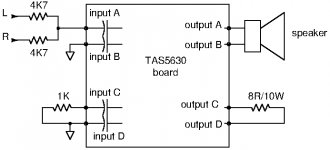
I tried to draw up the connections for the board if it uses single line input (phase inverter onboard). If the inputs are balanced, you may need to do the mono summing before the phase inverter.
Attachments
Last edited:
The 1K should absolutely not heat as it is on the input side of the input coupling capacitors.
Would you know if the board uses single line input signal or balanced lines input signal?
I tried to draw up the connections for the board if it uses single line input (phase inverter onboard). If the inputs are balanced, you may need to do the mono summing before the phase inverter.
Sorry, my mistake, I meant the 8R/10W got really hot... Single line input, board matches your diagram. Thanks.
if you don't connect a speaker to the second channel the output filter choke will ring at very high voltages and possibly fry the output filter capacitor.
Depending on how conservative the voltage of the capacitor is will decide if it fries or not.
The filter's resonance should be well below the switching frequency since its at the roll-off knee of the damped response, hopefully vaguely around 20kHz. So if the input is unused it shouldn't be a problem as there won't be 20kHz energy.
A class D amp with feedback loop including the filter will be able to tame such a resonance perhaps - I guess the interesting scenario is tweeter failing at high power - does the filter cap follow?
I guess its not hard to rate the capacitor conservatively anyway.
I've certainly run a cheap TDA7498 board single-channel for many weeks without issues.
A class D amp with feedback loop including the filter will be able to tame such a resonance perhaps - I guess the interesting scenario is tweeter failing at high power - does the filter cap follow?
I've certainly run a cheap TDA7498 board single-channel for many weeks without issues.
I am talking about an irs2029 based system with pre filter feedback so the ringing will have no effect on the feedback.
I have scoped it and the ringing is massive without a speaker.
Sometimes the 2092 will simply stop oscillating and the output sits at 17VDC.
Sorry, my mistake, I meant the 8R/10W got really hot... Single line input, board matches your diagram. Thanks.
Could it be that you have disabled the input corresponding to the speaker output and send music to the 8R/10W?
If so, you may hear some weak music in the speaker due to coupling from the other channel.
Could it be that you have disabled the input corresponding to the speaker output and send music to the 8R/10W?
If so, you may hear some weak music in the speaker due to coupling from the other channel.
No, the only think I did different is short the input with. 4k7 instead of 1k, but I don't see why that would lead to the 8R/10W to run hot.
No, the only think I did different is short the input with. 4k7 instead of 1k, but I don't see why that would lead to the 8R/10W to run hot.
I fully agree with you. If you disable the input to one channel (before the coupling capacitors) that channel should be silent even with a speaker connected to it. Did you try to measure if there is a DC voltage across the 8R/10W resistor?
- Status
- Not open for further replies.
- Home
- Amplifiers
- Class D
- Class D Stereo Amp in Mono?