I made a mistake Perry, and don’t know how I confused it, I doubt it changes anything but I mistakingly thought this was the HCCA 8000.1D, it is actually the HCCA 11000.1D, I apologize.
And I’m sure the PS riser card has to be installed, but I want to make sure as I’ll have to rig up or order some extension leads (finally) to test the pins with the Power Supply riser card installed, as they are under it.
That is correct right? PS needs to be fully functional (riser card installed) to get the correct voltage reading on these pins?
Ty for helping me with this btw, I was under the gun on some stuff but am now more situated where I can reply more then once a day 😅
Why do you need to have the PS driver board on extensions? Does it interfere with getting the voltages?
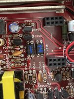
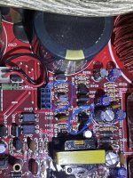
Yes, these 2 octocouplers are directly under the PS riser card. I’m on Amazon looking for a set of probes/leads now
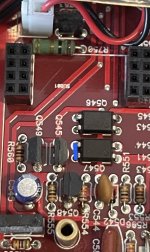
I wish I checked this earlier, I’ve been waiting for my new leads …turns out I don’t even need them 🤦🏼 Also, I had forgotten about this, when I first pulled the board checking and cleaning up the solder work, etc there was a solder bridge near fan area I remember cleaning up. After reading your last post and getting ready to try from underneath i remembered that solder bridge (I always mark corrections, etc jic) and turns out that solder bridge connected these 2 leads (in pic as blue line). This has to be something either intentional or what could have caused the problem right? I’m setting up now for testing as you instructed.
I almost want to try reapplying that solder bridge, as the amp was running since factory with it and it was “fine” working for awhile, only reason I have it is heavy vibration damage, etc. but I think I’ll wait for your reply 😅
I almost want to try reapplying that solder bridge, as the amp was running since factory with it and it was “fine” working for awhile, only reason I have it is heavy vibration damage, etc. but I think I’ll wait for your reply 😅
Attachments
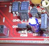
Find the two 2N7000 transistors in that area that have leg 3 connected tp pin 2 of those 2 optocouplesr.
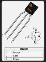
Does the drain of those two 2N7000s go to pin 3 of the two optocouplers (likely through a resistor)?
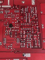
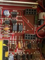
Yes, Drain of Q544 has direct continuity to pin 3 of Q547.
Drain of Q543 eventually leads to Pin 3 of Q546 through a resistor via shared trace.
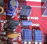
Pic of underside, marked, even tho I know it’s only half the board, just for note, prolly not needed or very useful but including it.
Drain of Q543 eventually leads to Pin 3 of Q546 through a resistor via shared trace.
Pic of underside, marked, even tho I know it’s only half the board, just for note, prolly not needed or very useful but including it.
Attachments
Shouldn't:
Drain of Q543 eventually leads to Pin 3 of Q546 through a resistor via shared trace.
be:
Drain of Q543 eventually leads to Pin 2 of Q546 through a resistor via shared trace.
Drain of Q543 eventually leads to Pin 3 of Q546 through a resistor via shared trace.
be:
Drain of Q543 eventually leads to Pin 2 of Q546 through a resistor via shared trace.
Wow I mistyped. Sorry, you are correct Perry. I will double check my posts before hitting “post”
When you read -8.5v, did you have the black probe on the source leg?
If those are the only two 2N7000s in the amp, I think the jumper on the optocoupler may have been to cover a mistake in the board layout.
If those are the only two 2N7000s in the amp, I think the jumper on the optocoupler may have been to cover a mistake in the board layout.
Yes, after looking at how I had the board I know I didn’t switch the leads around when going from one to the other, and I would have had to. I will make sure I note that from now on for future probings.
And ya it looked on purpose from factory. I’m going to try it, might as well, I’ll report back once I do. I also know a few who may have 11k same version amps, to ask if it also has it jumped.
Ty Perry, brb!
And ya it looked on purpose from factory. I’m going to try it, might as well, I’ll report back once I do. I also know a few who may have 11k same version amps, to ask if it also has it jumped.
Ty Perry, brb!
Wow, yup, that was it Perry, relays kicked on and amp is working 100% …now I understand why alot of ppl say some of Orions protection circuit “never worked” …will def have to remember this.
Thx again for going through this with me, hope to someday be at even half your level 🖖🏼
Take care!
Edit: So I wrote that right after I got relays to kick on, but after I went back to test and make sure all is good, amp is pulling more then my 10a PSU can give, at idle, no inout signal, soon as amp boots up fully relays kicking on. Usuall an amp of this size only pulls about 8a at idle I think? I’m goin to try my 90amp PSU but could that circuit cause higher idle amperage draw?
Last edited:
- Home
- General Interest
- Car Audio
- Class D Speaker Output Relay?