Hey all🙂
im new to this site but im in desperat need of help with my class D project.
I have constructed the reference IRAUDAMP7S from IRF.com but i cant get it to work.
when i sweep the input signal (1kHz) from 20mVpp to 80mVpp its a fine looking sine wave on the output after the LPF.
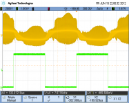
From the 80mVpp the amplitude has now reached 1.2Vpp(the gain is 15), then the amplitude stops to increase when I increase the input voltage, now instead of increasing the amplitude of the signal the signal gets more and more flat looking with a lot of spikes.
I cant find out what the problem is, does anyone know what to do?=)
the scoop picture: the green is the reference signal som the sine generator, the yellow is the input signal above 80mVpp.
im new to this site but im in desperat need of help with my class D project.
I have constructed the reference IRAUDAMP7S from IRF.com but i cant get it to work.
when i sweep the input signal (1kHz) from 20mVpp to 80mVpp its a fine looking sine wave on the output after the LPF.
From the 80mVpp the amplitude has now reached 1.2Vpp(the gain is 15), then the amplitude stops to increase when I increase the input voltage, now instead of increasing the amplitude of the signal the signal gets more and more flat looking with a lot of spikes.
I cant find out what the problem is, does anyone know what to do?=)
the scoop picture: the green is the reference signal som the sine generator, the yellow is the input signal above 80mVpp.
Attachments
Last edited:
Hey all🙂
im new to this site but im in desperat need of help with my class D project.
I have constructed the reference IRAUDAMP7S from IRF.com but i cant get it to work.
when i sweep the input signal (1kHz) from 20mVpp to 80mVpp its a fine looking sine wave on the output after the LPF.
From the 80mVpp the amplitude has now reached 1.2Vpp(the gain is 15), then the amplitude stops to increase when I increase the input voltage, now instead of increasing the amplitude of the signal the signal gets more and more flat looking with a lot of spikes.
I cant find out what the problem is, does anyone know what to do?=)
the scoop picture: the green is the reference signal som the sine generator, the yellow is the input signal above 80mVpp.
The gain is 15? Check the feedback network (R7, R8)!!
You must use a higher gain, to the amplifier work stable.
according to the reference design the gain is a product of the total input impedance which is R2+R7. the total gain is then calculateted as R8/(R2+R7).
R2 is part of an LPF which i have recalculated because it dident make sense to me that the corner frequency is 500kHz, so i change it to R2=3.09k C2=2n which gave me a corner frequency at 25.8kHz, i did it to eliminate noise.
thats why the gain is 15 now.
but the problem with the output was also there before i change the LPF on the input.
The input seems to clip at 200mV - or do you use a 1:10 probe?
What's the supply voltages?
I assume the green trace is the sync signal, not the input signal. Is the input signal a sine wave?
jan didden
What's the supply voltages?
I assume the green trace is the sync signal, not the input signal. Is the input signal a sine wave?
jan didden
Strange, maybe something's wrong with the generator, like it doesn't like conducted HF ripple reflected to input or through ground. Have you checked other sources, preferably floating?
By the way how can you see a 1.2V "nice sine" on the output of switching amplifier? How high is a HF ripple on output?
By the way how can you see a 1.2V "nice sine" on the output of switching amplifier? How high is a HF ripple on output?
Last edited:
the input is 150mVpp in the picture. and yes sry im using a 1:10 probe. the supply voltage is -30V and +30V.
the HF ripple on the output is 3V as i see it on the picture, or what do u meen??
the "nice sine wave" is after the LPF on the output and only when the input signal is 80mVpp or below, when i sweep above the 80mVpp the amplitude dosent get higher like it should, and thats what i cant figure out how to solve=/
- Status
- Not open for further replies.
- Home
- Amplifiers
- Class D
- class D problem plz help