Hi,
I want to use class d amp for my subwoofer .... 20-500Hz bandwidth ..
Is there any problem to make output LP filter to cut frequency from 10 or 15 KHz and up ??
My amp if full bridge, single supply and I have 60 uH inductors on 'stock' that can not be modified ..., 8 ohm speaker ??
Thank you in advance,
Emil
It is usual to remove frequencies you don't want before the amplifier.
A sub would require a cut off point at around 100HZ.
A simple RC network would give you somewhere near it. F=1/2pii RC
A sub would require a cut off point at around 100HZ.
A simple RC network would give you somewhere near it. F=1/2pii RC
The output filter on a Class D amplifier is there to prevent RF interference. It clearly needs to start above the audio bandwidth you are using, but it does not need to start immediately. Hence a subwoofer amp going up to 500Hz will be fine with an output filter starting from many 10's of kHz.
The output filter should not start too low, as it can be difficult to make a filter effective over a really wide bandwidth. The aim is to filter away signals in the high kHz and low MHz region - say 50kHz to 20MHz. This is a ratio of 400. A similar circuit designed to start at 1kHz would only go up to 400kHz so you would need a second filter to do the rest.
The output filter should not start too low, as it can be difficult to make a filter effective over a really wide bandwidth. The aim is to filter away signals in the high kHz and low MHz region - say 50kHz to 20MHz. This is a ratio of 400. A similar circuit designed to start at 1kHz would only go up to 400kHz so you would need a second filter to do the rest.
Hi
Thank you for your answers,
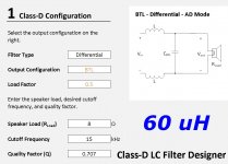
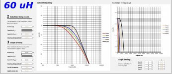
I have made some calculations ... for 60 uH inductor + 1 uF cap... for my sub amp...
Cutoff is about 15 KHz .... Please see pics ..
If this amp is for use only with subwoofer is there any problem that LP filter pass frequency up to 15 KHz ??
OR ... is there any problem with the sound quality when using class d amp with this LP filter when it is just for subwoofer ?? 🙂
Regards,
Emil
Thank you for your answers,
I have made some calculations ... for 60 uH inductor + 1 uF cap... for my sub amp...
Cutoff is about 15 KHz .... Please see pics ..
If this amp is for use only with subwoofer is there any problem that LP filter pass frequency up to 15 KHz ??
OR ... is there any problem with the sound quality when using class d amp with this LP filter when it is just for subwoofer ?? 🙂
Regards,
Emil
Attachments
Thank you for your answers,
I have made some calculations ... for 60 uH inductor + 1 uF cap... for my sub amp...
Cutoff is about 15 KHz .... Please see pics ..
If this amp is for use only with subwoofer is there any problem that LP filter pass frequency up to 15 KHz ??
OR ... is there any problem with the sound quality when using class d amp with this LP filter when it is just for subwoofer ?? 🙂
Regards,
Emil
Do you also stop your car by sticking your foot out the door as opposed to using the brake pedal?
The output filter on a Class D amplifier is there to prevent RF interference. It clearly needs to start above the audio bandwidth you are using, but it does not need to start immediately. Hence a subwoofer amp going up to 500Hz will be fine with an output filter starting from many 10's of kHz.
It also is there to reduce Eddy currents in the core, coils and magnets of the speaker.
Rising inductance of the sub-woofer driver will effectively unload it from the amplifier at high frequencies anyway. I don't really see what practical objective this output filter would be capable of solving.
Dave.
Dave.
It depends on type of modulator.
Post-filter feedback will correct the frequency response of the filter, although a too low cutoff with a too low impedance load at HF (low relative to filter impedance) will result in premature clipping.
Pre-filter feedback for driving an inductive transducer will always result in some HF peaking, unless a custom RC damper is used. A LF speaker driver can easily exhibit 1mH inductance at f'=1khz, although it is not constant with frequency (more likely Z=2*pi*f*L*sqrt(f'/f), 3dB/oct, rather than Z=2*pi*f*L, 6dB/oct). But this HF peaking can happen above audio band (but increasing switching frequency requirements and lowering efficiency) or well above speaker passband (favorable case, subwoofer-only amplifier).
So for your case (LF speaker driver load, pre-filter feedback I assume) output filter design is more about output coil size, core losses, and amount of carrier residual allowed. Lower inductance increases peak-to-peak inductor current but reduces discontinuous-to-continuous-conduction distortion characteristic from dead time in class D. Lower inductance also increases core losses, so it is a matter of picking a core size, then picking an inductance value resulting in not too hot coil when idle for desired switching frequency (and with room for desired wire gauge for coil not too hot and full music power), then picking output capacitors (I recommend 3 caps for full bridge), then adding a RC damper (with 3W resistor to handle any HF burst, although losses in normal operation will be low), the damper is recommended because with a high inductance LF driver peaking can be quite severe, and LF drivers occasionally have HF peaks too that must remain hidden, the RC reduces worst case peaking to reasonable amount of dB (but the lower the resonant freq of the filter and the lower the L value the bigger the C required and the lower R value).
Last edited:
Hello !
Thank you for your time and answers !
Let me to add some more important information as base ..
Your answer are too complicated for me ... 🙂
My plan is to build this amp - many channels for each speaker / subwoofer:
1.
Ratmayor's Blog
2. I want to pass only 0-500 Hz to this amp from ADAU1701 crossover ..
3. I have 60 uH toroids .. and they cost money ...
4. again ... If I build this schematic / amp ... with LP filter with 15 kHz cutof ... is it a bad idea ? I mean bad sound quality ???
( Is there any difference from the same amp with cutoff LP filter ... in example 22 uH ... and 3.3 uF ...)
THANK YOU
Emil
You need to calculate filter components keeping in mind, first, the frequency of cutoff (-3dB), and the load impedance (Any online calculator will give you the values needed). Second, rate them on a power capability basis. Perhaps, with lots of luck, the 60µH can perform, but it is most probable that doesn't.
Find another schematic, that one is really bad, it lacks power rail decoupling and snubbers, and the modulator is plain old triangle wave without integrator resulting in quite limited error correction capability. Check threads about IRS2092.
A picture of the toroids could help to determine suitability, is manufacturer/brand known? The 60uH value is not a problem, toroids are easy to rewind (inductance is proportional to turns^2 so removing half turns would result in 15uH), or do you mean MPP cores with 60u permeability (btw:these are the highest cost ones)?
A picture of the toroids could help to determine suitability, is manufacturer/brand known? The 60uH value is not a problem, toroids are easy to rewind (inductance is proportional to turns^2 so removing half turns would result in 15uH), or do you mean MPP cores with 60u permeability (btw:these are the highest cost ones)?
Thank you Eva,
I have my power supply ready .. it is single supply +50 VDC - I want to use it 🙂
( large one + expensive caps ... etc.... )
If this schematic is bad can you give a link to good one ... single supply, full bridge ( h-bridge ) for subwoofer ... ( 8 ohm ) ... it can be IRS2092 or with any other mosfet drivers .. IR2184 .. etc ... for 0-500 Hz ... ??
my inductors .. :
https://www.digikey.co.uk/product-d...cs-corporation/PE-51508NL/553-1723-ND/2265974
Regards,
Emil
These inductors are swinging chokes, inductance changes 2:1 from zero current to maximum current, as for a SMPS, not good for class D, particularly not good for the schematic proposed due to low error correction ability, huge/overpriced/overkill coil too:
http://productfinder.pulseeng.com/products/datasheets/P589.pdf
This is a source for micrometals -2 material toroids, one of the most suitable choices for class D:
Toroids, Ferrites, Parts, Kits, Toroid King, QRP Erector Set
At 50V single supply there are chips that can do the work:
https://www.ebay.com/sch/i.html?_od...l1313&_nkw=class+D+power+amp+TAS5630&_sacat=0
WONDOM 1X 500W Class D Audio Amplifier Board Compact T-AMP Mono Subwoofer | eBay
Even if you want to do the amplifier yourself, take a look at datasheet of these chips, discrete may not be the best approach in this case (for a first project).
Hi
Hello Eva,
Thank you for the info !
May I ask for link .. info, schematic, pdf .. etc .. for discrete, high quality sub class d amp for single supply about 50-60 V ???
Or ... If I am using full h-bridge on the output of the amp .. what kind of input stage is good for quality sub amp .. any links ?? .. sch ... pdfs .. ?? 🙂
Thank you in advance,
Emil
For 50V there are ready-made IC solutions.
For next step study schematics in Behringer service manuals:
Behringer 1400W Class D for B1800D Repair help!!
And look for INUKE 3000 service manual too.
For next step study schematics in Behringer service manuals:
Behringer 1400W Class D for B1800D Repair help!!
And look for INUKE 3000 service manual too.
May I ask for link .. info, schematic, pdf .. etc .. for discrete, high quality sub class d amp for single supply about 50-60 V ??? Emil
Discrete? Take a look at this one.
It is from my own idea, ask me for the circuits in Xpress Schematic file format. Easy and quick to put to work, and standard parts.
help ..
Hello,
I found this schematic and PCB .. ( second one .... Posted July 29 )
Усилители Мощности Класса D - Страница 307 - Усилители мощности класса D - Форум по радиоэлектронике
http://forum.cxem.net/uploads/month...99_-.GIF.d60dd19f8065b50ebe5d0211ce89bf68.GIF
Is it a UCD class D amp ? can someone help me to check the class d type ??
Thank you in advance !!
Emil
- Status
- Not open for further replies.
- Home
- Amplifiers
- Class D
- class d output LP filter