I'm experimenting with output inductors on my class D amp (irs2092 based). 6x 4227 output FETs switching around 200kHz. Output stage is more than capable of over 1kW of power but my power supply is the limiting factor so I detune to around 700 watts at 1 ohm.
As others have experienced on here, using power inductors will cause them to get hot. Many people here like to recommend T106-2 as well.
However, I harvested an inductor from a old amplifier that uses double stacked black cores with 17 turns with dimensions - diameter: 30mm, ID: 13mm, H: 23.5mm (height is total height of stacked core) with an inductance of ~33uH. This inductor runs very cool (50C max). What type of core do you think this is? Plugging the values into coil64 program, it seems to have a Mu' of ~30. Whereas cores like T106-2 has a Mu' of 10.
I also tried fair-rite material 68 (https://www.digikey.com/en/products/detail/fair-rite-products-corp/5968002701/8599644) which has very similar specs to T106-2 but it got very hot (over 120C). I wrapped it with about 45 turns of 5 parallel 20AWG wire to get about 40-45uH. Material 68 is NiZn instead of iron powder of T106-2, would this be the cause of it getting hot?
I would like to try T106-2 core but it seems I can only get them on ebay at the moment, ideally I'd like to be able to buy from digikey or mouser.
700W at 1 Ohm is 1 kA peak. Do you really mean this? My high current (much lower than that) smps inductors use a flat tape
Yeah, I see what you mean. It is 1 ohm speaker load, not resistive when I measured during testing.
Edit: I think Im not understanding where you are getting the 1kA value from?
Edit: I think Im not understanding where you are getting the 1kA value from?
Last edited:

1kA with 45 turns is a lot of flux in the core - it is likely saturating at much lower levels than this. I would look at the core temperature versus output power level while putting a sine wave into the amp and drive resistive load. The frequency plays a role as well. The wire must be getting quite warm as 5 parallel 20awg wires is undersized for such high currents.
Powdered iron cores like T106-2 have a distributed air gap as well as higher Bsat than ferrites, and that allows them to handle higher currents. There are a number of large iron powder core types out there, but not carried by Digi or Mouser.
Powdered iron cores like T106-2 have a distributed air gap as well as higher Bsat than ferrites, and that allows them to handle higher currents. There are a number of large iron powder core types out there, but not carried by Digi or Mouser.
20 AWG is rated at 6A. Five in parallel 30A and then derate a lot as being wound in a core traps the heat, certainly no more than 10A.
1 kA should start a fire.
Also 700W into 1 Ohm is 700V rms. I don't see how 200V mosfets can do this.
1 kA should start a fire.
Also 700W into 1 Ohm is 700V rms. I don't see how 200V mosfets can do this.
P=I^2 * R so 1kA peak would mean 1 MW peak !!! 😉700 Wrms are 1 kW peak.
1 kW peak on 1 Ohm is 1 kA peak.
Regards
Charles
If my power rails are +/- 70V, and 70V/1.414 = ~50Vrms. Then 50^2/(Rload) = power. 50^2/2 = 1250W. 1250W/50V = 25Arms, no?
I should have mentioned that the inductor is getting hot at idle, not driving a load.
I should have mentioned that the inductor is getting hot at idle, not driving a load.
Thanks for actually providing useful information. I went ahead and bought some T106-2 cores on ebay. I wasn't aware they had an air gap. I'm just trying to figure out what core materials can be used without getting hot.1kA with 45 turns is a lot of flux in the core - it is likely saturating at much lower levels than this. I would look at the core temperature versus output power level while putting a sine wave into the amp and drive resistive load. The frequency plays a role as well. The wire must be getting quite warm as 5 parallel 20awg wires is undersized for such high currents.
Powdered iron cores like T106-2 have a distributed air gap as well as higher Bsat than ferrites, and that allows them to handle higher currents. There are a number of large iron powder core types out there, but not carried by Digi or Mouser.
There are many amps out there that do over 1000W into 1 ohm with the irfb4227 FETs - rockford fosgate r1200.1d, for example.20 AWG is rated at 6A. Five in parallel 30A and then derate a lot as being wound in a core traps the heat, certainly no more than 10A.
1 kA should start a fire.
Also 700W into 1 Ohm is 700V rms. I don't see how 200V mosfets can do this.
Both wrong.
700W rms is 1400W peak, the peak power is twice the average for a sine wave.
1kW into 1ohm is 44.7V peak (and 44.7A peak of course).
P=IV, V=IR, so I = sqrt(P/R), V = sqrt(PR)
peak V = sqrt(2) x Vrms
peak I = sqrt(2) x Irms
peak P = 2 * Vrms * Irms
Can you provide a schematic?I should have mentioned that the inductor is getting hot at idle, not driving a load.
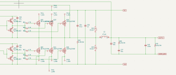
Here's the output section.
Previously, I used a MnZn power inductor (rated for 125C) for the output filter that reached 115C just idling for 1 hour. Despite being so hot, it worked fine. Using the inductor I got from a old amp it only reaches ~50C after 1 hour of idling. Even when driving a speaker at about 400 watts (music) for 30 minutes it only got up to ~65C.
Previously, I used a MnZn power inductor (rated for 125C) for the output filter that reached 115C just idling for 1 hour. Despite being so hot, it worked fine. Using the inductor I got from a old amp it only reaches ~50C after 1 hour of idling. Even when driving a speaker at about 400 watts (music) for 30 minutes it only got up to ~65C.
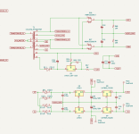
Attachments
Ferrites tend to deteriorate with heat, becoming more lossy and getting even hotter. Over hot is an indication the core is too small for the job, or the wrong ferrite. There are many formulations and each has a different loss v. frequency curve.
Material 68 is NiZn instead of iron powder of T106-2, would this be the cause of it getting hot?
It would have been great if the datasheet showed the material performance curves showing the core flux vs frequency and other parameters like permeability vs frequency but otherwise just test it and find out whether the material works it sounds like the core is used for energy storage applications like filters/buck/boost converters under 100KHz.
Anyway - There are tons of posts in the past proving that ferrite material core are not being sustainable for class-d @ +200KHz.
The output inductor has no visible current path (AUDIO_GND appears to go nowhere). Where does it connect off the photo? please add that rest of the ckt.Here's the output section.
Previously, I used a MnZn power inductor (rated for 125C) for the output filter that reached 115C just idling for 1 hour. Despite being so hot, it worked fine. Using the inductor I got from a old amp it only reaches ~50C after 1 hour of idling. Even when driving a speaker at about 400 watts (music) for 30 minutes it only got up to ~65C.
On fair-rite's website it has more information on the material, including the freq vs. permeability curve. https://fair-rite.com/68-material-data-sheet/Material 68 is NiZn instead of iron powder of T106-2, would this be the cause of it getting hot?
It would have been great if the datasheet showed the material performance curves showing the core flux vs frequency and other parameters like permeability vs frequency but otherwise just test it and find out whether the material works it sounds like the core is used for energy storage applications like filters/buck/boost converters under 100KHz.
Anyway - There are tons of posts in the past proving that ferrite material core are not being sustainable for class-d @ +200KHz.
AUDIO_GND is the center tap to my rail capacitors.Tony Salsich:
The output inductor has no visible current path (AUDIO_GND appears to go nowhere). Where does it connect off the photo? please add that rest of the ckt.
Attachments
Then it would appear that the circuit maintains zero volts average at the output (during idle) by driving the half bridge at 50% duty (average half bridge voltage must be 1/2 bus), and if the pulse width is maxed (50% duty for upper and lower section, but out of phase of course), then this pumps current in and out of the inductor at 200kHz. The net voltage across the inductor may be zero but the ripple current content will be composed of ~1.12Arms at 200kHz; ~125mArms at 600kHz; ~45mArms at 1MHz and so on (assuming exactly 50% duty and assuming that the inductor value is constant at these frequencies). This should indeed result in a warm inductor at idle.AUDIO_GND is the center tap to my rail capacitors.
BTW; most ferrite materials run 'warm' as their losses tend to hit a minimum at elevated temps.
Last edited:
It is time to ditch your pocket calculator20 AWG is rated at 6A. Five in parallel 30A and then derate a lot as being wound in a core traps the heat, certainly no more than 10A.
1 kA should start a fire.
Also 700W into 1 Ohm is 700V rms. I don't see how 200V mosfets can do this.
Yep, I see the error, 200V mosfets on 70V rails is a sensible maximum. Then you get 50Vrms, which is 2.5 kW into 1 OhmIt is time to ditch your pocket calculator
This is 50A rms, which is still far too much for the inductor wire size.
- Home
- Amplifiers
- Class D
- Class D Output Inductor