Hey DAers,
I'm currently trying to learn something about coilcores in outputfilters.
I'm having a 1500W in 4 ohm Subwoofer, (120V single supply)
My output filter is constructed out 47uH coils and 1u5F capacitors.
Where do I find information about calculting the saturation etc.?
Or how can I choose wisely?
I'm currently trying to learn something about coilcores in outputfilters.
I'm having a 1500W in 4 ohm Subwoofer, (120V single supply)
My output filter is constructed out 47uH coils and 1u5F capacitors.
Where do I find information about calculting the saturation etc.?
Or how can I choose wisely?
An important data is frequency, voltage and current in the inductor. Normally a N27 material go well up to 100KHz, but usually higher frequencies requieres lower permeability ferrites, NOT GAPPED, and more turns than lower freq. There are several interesting in the web.
I can send a copy of ones that helped in my design.
I can send a copy of ones that helped in my design.
with those kinds of currents, air-core would be the safest...only issue is kind of a large leakage field...but maybe you can put it someplace it wouldn't matter so much, or use a toroidal winding geometry around an air core.
If you did it as a solenoid, then 92 turns on a 1" diameter cylinder that is
4 inches long gives 47.5 micro-Henries.
Here's the solenoid equation, due to Wheeler:
L=n^2*r^2/(9*r+10*l),
where L is inductance in micro-Henries.
r is radius in inches
l is the length in inches
n is the number of turns
If you did it as a solenoid, then 92 turns on a 1" diameter cylinder that is
4 inches long gives 47.5 micro-Henries.
Here's the solenoid equation, due to Wheeler:
L=n^2*r^2/(9*r+10*l),
where L is inductance in micro-Henries.
r is radius in inches
l is the length in inches
n is the number of turns
Inductor Design Software
RF Design Software
Download
--Filesize ~1.5 MB
Click Here to Download
Inductor Design Software 2010 (MicroRelease_March2010.exe)
Download
--DOS version
--Filesize ~400K
Click Here to Download
RF Design Software (Toroid.zip)
Micrometals, Inc. has thoroughly reviewed this design software and the equations utilized to calculate the suggested windings and believe the information to be accurate. It is important to note that the default settings can be altered and unacceptable designs generated. Before using this product, the buyer agrees to determine suitability of the product for their intended use or application. Micrometals shall not be liable for any loss or damage, including but not limited to incidental or consequential damages as a result of the use of this software.
Micrometals will gladly offer engineering assistance and provide samples to aid in your core selection, please do not hesitate to contact your local representative or the factory directly.
The updated version offered here includes new materials.
Micrometals Inductor Software is a flexible user friendly tool designed to assist in the selection of iron powder cores. The software file size is 1.5 MB.
The user will have the opportunity to select from five different inductor applications:
1) Design of DC output inductors Differential mode inductors
2) Design of controlled swing inductors where the inductance does not exceed a maximum value at reduced current.
3) Design of wide swing inductors utilizing a composite core of ferrite and iron powder.
4) Design of a power factor boost or buck inductor, commonly referred to as a PFC choke.
5) Design of 60 Hz dimmer inductor
6) Design of a Resonant Converter Inductor
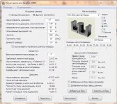
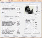
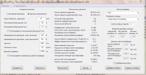
The program accepts user defined design requirements in terms of required inductance, dc resistance, dc bias current and applied ac voltage. The user has the option of specifying core geometry (i.e. Toroid, E-Core or Ferrite/Iron Powder Composite), specific core materials or all materials, metric units or English units, maximum window fill factor, temperature rise, ambient temperature, etc.
This program will automatically calculate the smallest core size possible and will display;
1) Micrometals Part Number
2) Approximate unit price
3) Core AL Value
4) Required Number of Turns
5) Wire Size
6) Percent Window Fill
7) DC Winding Resistance
8) B ac
9) Percent Initial Permeability
10) Core Loss
11) Copper Loss
12) Temperature Rise.
In addition, new features alow the user to analyze specific designs as well as check the core's operating temperature vs. time for thermal aging analysis of designs.
The software allows the design engineer to quickly work up multiple design solutions based on user specified electrical requirements which all can easily printed for hard copies. Designs can also be saved to a file by using the 'F' key.
The following are definitions of the units utilized by the design software:
Unit
Description
Defined
AL
Inductance Rating
Nanohenries per turn squared (nH/N2)
Price
US Dollars
Approximate value at 2,500 pieces
RDC
DC Resistance
Ohms
BAC
Peak AC Flux
Gauss
P FE
Core Loss
Watts
P CU
Copper Loss
Watts
T Rise
Temperature Rise
Degrees Celsius
The design program is automatically set to default to an ambient temperature of 25°C in free standing air with maximum temperature rise of 40°C.
Micrometals Inductor Software is a flexible user friendly tool designed to assist in the selection of iron powder cores. The software is a DOS based program with a file size of 250KB.This version "2000b" of the design software is for 'beta' release only.
Please contact Micrometals if you require technical support regarding the use of this software or our product line. Micrometals will also gladly offer sample cores to assist in your core selection.
RF Design Software
Download
--Filesize ~1.5 MB
Click Here to Download
Inductor Design Software 2010 (MicroRelease_March2010.exe)
Download
--DOS version
--Filesize ~400K
Click Here to Download
RF Design Software (Toroid.zip)
Micrometals, Inc. has thoroughly reviewed this design software and the equations utilized to calculate the suggested windings and believe the information to be accurate. It is important to note that the default settings can be altered and unacceptable designs generated. Before using this product, the buyer agrees to determine suitability of the product for their intended use or application. Micrometals shall not be liable for any loss or damage, including but not limited to incidental or consequential damages as a result of the use of this software.
Micrometals will gladly offer engineering assistance and provide samples to aid in your core selection, please do not hesitate to contact your local representative or the factory directly.
The updated version offered here includes new materials.
Micrometals Inductor Software is a flexible user friendly tool designed to assist in the selection of iron powder cores. The software file size is 1.5 MB.
The user will have the opportunity to select from five different inductor applications:
1) Design of DC output inductors Differential mode inductors
2) Design of controlled swing inductors where the inductance does not exceed a maximum value at reduced current.
3) Design of wide swing inductors utilizing a composite core of ferrite and iron powder.
4) Design of a power factor boost or buck inductor, commonly referred to as a PFC choke.
5) Design of 60 Hz dimmer inductor
6) Design of a Resonant Converter Inductor
The program accepts user defined design requirements in terms of required inductance, dc resistance, dc bias current and applied ac voltage. The user has the option of specifying core geometry (i.e. Toroid, E-Core or Ferrite/Iron Powder Composite), specific core materials or all materials, metric units or English units, maximum window fill factor, temperature rise, ambient temperature, etc.
This program will automatically calculate the smallest core size possible and will display;
1) Micrometals Part Number
2) Approximate unit price
3) Core AL Value
4) Required Number of Turns
5) Wire Size
6) Percent Window Fill
7) DC Winding Resistance
8) B ac
9) Percent Initial Permeability
10) Core Loss
11) Copper Loss
12) Temperature Rise.
In addition, new features alow the user to analyze specific designs as well as check the core's operating temperature vs. time for thermal aging analysis of designs.
The software allows the design engineer to quickly work up multiple design solutions based on user specified electrical requirements which all can easily printed for hard copies. Designs can also be saved to a file by using the 'F' key.
The following are definitions of the units utilized by the design software:
Unit
Description
Defined
AL
Inductance Rating
Nanohenries per turn squared (nH/N2)
Price
US Dollars
Approximate value at 2,500 pieces
RDC
DC Resistance
Ohms
BAC
Peak AC Flux
Gauss
P FE
Core Loss
Watts
P CU
Copper Loss
Watts
T Rise
Temperature Rise
Degrees Celsius
The design program is automatically set to default to an ambient temperature of 25°C in free standing air with maximum temperature rise of 40°C.
Micrometals Inductor Software is a flexible user friendly tool designed to assist in the selection of iron powder cores. The software is a DOS based program with a file size of 250KB.This version "2000b" of the design software is for 'beta' release only.
Please contact Micrometals if you require technical support regarding the use of this software or our product line. Micrometals will also gladly offer sample cores to assist in your core selection.
Hey DAers,
I'm having a 1500W in 4 ohm Subwoofer, (120V single supply)
A bridge?
And if you already have it running , whats the problem?
What cores do you have?
Hey DAers,
I'm currently trying to learn something about coilcores in outputfilters.
I'm having a 1500W in 4 ohm Subwoofer, (120V single supply)
My output filter is constructed out 47uH coils and 1u5F capacitors.
Where do I find information about calculting the saturation etc.?
Or how can I choose wisely?
An example for 1 kW:
http://www.diyaudio.com/forums/clas...00-watts-using-2-mosfets-163.html#post2901091
+ 1 info: saturation current= ~250 A*turn/mm for MnZn ferrites.
I recommend a big, gapped ferrite, stranded wire, keep distance from gap with wire! Iron powder can be also good, but generally harder to get the proper one (with low permeability and low loss).
Low permeability ferrite? What material? NiZn? Totally unsuitable (max 0.2 T)!
Air core? Induction heater!
A bridge?
And if you already have it running , whats the problem?
What cores do you have?
I have the bridge working but without the filter, simply cause I do not know jet which kind of coilcore to choose
Fullbridge 1500W (4 ohm)
It's a subwoofer --> 10 - 200 Hz
Last edited:
An important data is frequency, voltage and current in the inductor. Normally a N27 material go well up to 100KHz, but usually higher frequencies requieres lower permeability ferrites, NOT GAPPED, and more turns than lower freq. There are several interesting in the web.
I can send a copy of ones that helped in my design.
Would be great if you could send me copies, thanks
How can it work without an inductor?😱I have the bridge working but without the filter, simply cause I do not know jet which kind of coilcore to choose
Fullbridge 1500W (4 ohm)
It's a subwoofer --> 10 - 200 Hz
You are cheating somewhere ?
OK, you need the inductor with such values : 47uH , 30Amp (120V/4oHm) , withstanding frequency above 200kHz
I can suggest EDT59 core from Epcos , RM14 core from Epcos and T157-2 ring core.
Attachments
The amp can work without output filter, but at the cost of EMI and more moving coil heating. Be aware if you will drive line transformer speakers, high frequency will overheat iron cores and may burn both amp an xformer when no using output filters.
The amp can work without output filter, but at the cost of EMI and more moving coil heating. Be aware if you will drive line transformer speakers, high frequency will overheat iron cores and may burn both amp an xformer when no using output filters.
Maybe , if it's a pre-filter feedback🙂 , but if post-filter , like UcD , absolutely not 😀
Maybe , if it's a pre-filter feedback🙂 , but if post-filter , like UcD , absolutely not 😀
Absolutely not what? A RF high voltage will induce as much eddy currents in iron core lamination as to convert it into a big ball of boiling iron, ja ja ja....
I think that eddy current only affects windings , and no relation to the core 😀Absolutely not what? A RF high voltage will induce as much eddy currents in iron core lamination as to convert it into a big ball of boiling iron, ja ja ja....
A RF high voltage
How high is the voltage ? and we don't use RF in classD amps.😉
Get some education on classD basics.
I think that eddy current only affects windings , and no relation to the core 😀
A RF high voltage
How high is the voltage ? and we don't use RF in classD amps.😉
Get some education on classD basics.
Please, read carefully.
Radio frequency - Wikipedia, the free encyclopedia
Eddy current - Wikipedia, the free encyclopedia
Yes , you are right about wiki.
But i'll never, never, never call a 3kHz wave a Radio frequency😀.
So 2.99kHz is'nt a RF , and a 3kHz is ? 😱 Stupid.
P.S. Wikipiki is just like a gutter press .
Last edited:
Be aware if you will drive line transformer speakers, high frequency will overheat iron cores
These cores have great inductance , so the current of the high frequency will be miserable 😉
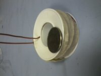
Enclosed picture is of an air core inductor made with 16 AWG magnet wire. I've placed a quarter on top to give a sense of scale. The coil form is an empty teflon tape spool. The inductance is 380 uH, the DC resistance is 0.25 Ohms. If you dropped the turns down enough to hit 47 uH, you would have just 0.088 Ohms of resistance. Given 1200 Watts into 4 Ohms, the inductor would dissipate less than 2.5 Watts...that would be pretty reasonable.
You could even use heavier gauge wire and still fit it, as it would have about 1/3 the number of turns of the coil in the picture...that would probably give you lower DCR.
Cell phone picture...not great...sorry!
You could even use heavier gauge wire and still fit it, as it would have about 1/3 the number of turns of the coil in the picture...that would probably give you lower DCR.
Cell phone picture...not great...sorry!
Attachments
Enclosed picture is of an air core inductor made with 16 AWG magnet wire. I've placed a quarter on top to give a sense of scale. The coil form is an empty teflon tape spool. The inductance is 380 uH, the DC resistance is 0.25 Ohms. If you dropped the turns down enough to hit 47 uH, you would have just 0.088 Ohms of resistance. Given 1200 Watts into 4 Ohms, the inductor would dissipate less than 2.5 Watts...that would be pretty reasonable.
The calculation is totally wrong, first of all you missed a zero! Not 2.5, but 25W!
And you ignored eddye current. AC flux penetrates into the wires, and induces very strong current, much stronger than the exciting current. It will be very hot at idle already! (Except if there is BD modulation, and choke filters only differential mode.)
Guilty as charged...I looked back at my calculation...found the off by 10! I^2*R with 1200 watts in the 400 Ohm load would be 25 Watts.
Let's see...If indeed you used only 1/3 the turns, you'd be at about 8.3 watts, neglecting eddy current losses.
I guess I was just curious to see, given that large power, what you might have to do to be practical...
Let's see...If indeed you used only 1/3 the turns, you'd be at about 8.3 watts, neglecting eddy current losses.
I guess I was just curious to see, given that large power, what you might have to do to be practical...
- Status
- Not open for further replies.
- Home
- Amplifiers
- Class D
- Class D output filter coil