Hi, i want to design an H bridge class d amplifier with the ability to digitally program the output current to the loudspeaker. The voltage should reamain constant.
Any ideas or schematic diagram from which start with this design?
I've found some articles on current-mode class d amp but i don't understand if they are suitable to my scope.
Current mode Class D for 160 meters, 80 meters, 40 meters
Could you help me?
Any ideas or schematic diagram from which start with this design?
I've found some articles on current-mode class d amp but i don't understand if they are suitable to my scope.
Current mode Class D for 160 meters, 80 meters, 40 meters
Could you help me?
Class D is basically a switch. Either on or off. Limiting the current will be a problem. Use the load as the limit in the normal way or measure the current return from the load, convert it to a voltage and switch the output stage off when the limit is exceeded. It will be either on or off, not reduced or expanded.
The article you included is ideal for RF transmitters as they use a tuned circuit and load through the aerial.
The article you included is ideal for RF transmitters as they use a tuned circuit and load through the aerial.
You can decrease or increase the current by changing the voltage or by changing the load.
If you are keeping the voltage "constant" then the current is determined by the load.
Your only option in that case would be to introduce more resistance in the load path.
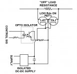
A few digitally controlled FET shunted resistors would work.
An isolated current sense method would need to be used in the case of an H bridge drive.
Interesting design challenge.
")
If you are keeping the voltage "constant" then the current is determined by the load.
Your only option in that case would be to introduce more resistance in the load path.
A few digitally controlled FET shunted resistors would work.
An isolated current sense method would need to be used in the case of an H bridge drive.
Interesting design challenge.
...
A digitally controlled FET shunted resistors seems to be a good idea...how could i find that?
Thanks
Build a few of these with 1R, 2R, 4R series to get the max and min value you need.
Attachments
Last edited:
- Status
- This old topic is closed. If you want to reopen this topic, contact a moderator using the "Report Post" button.