Hello!
I have a home theater subwoofer that I bought new a few weeks ago and thought I would test this amplifier's rated power using my oscilloscope. The company claims their class D amplifier should output around "500 watts RMS", but the problem is I'm not getting anywhere near that. I'm definitely not as experienced as a lot of you on here are and hoping that one of you might be able to help me.
How I'm testing this amplifier is by having my signal generator send a 75Hz signal to my preamplifier, which then sends that signal to the subwoofer via the sub out connection. I then have a 4 ohm dummy load connected to the subwoofer's plate amplifier and the probe from oscilloscope is connected to the positive wire. Since most class D amplifiers use bridging of some sort to obtain higher power I'm always reluctant to connect the ground wire from my probe to the negative side of the output in fear that it might short it out. Because of this, the ground lead off the oscilloscope probe was disconnected for this test. Could having the probe's ground wire disconnected be causing inaccuracies in my measurements?
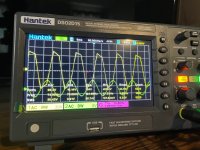
Enclosed is a screenshot from my oscilloscope showing the amplifier clipping. If I can keep the voltage around 31 volts or below, then clipping is not an issue. This would mean this amplifier has an average power of around 240 watts if I did the math correctly (31*31/4)? I know the company is using RMS values but average power shouldn't be that much lower, right?!
Thanks
I have a home theater subwoofer that I bought new a few weeks ago and thought I would test this amplifier's rated power using my oscilloscope. The company claims their class D amplifier should output around "500 watts RMS", but the problem is I'm not getting anywhere near that. I'm definitely not as experienced as a lot of you on here are and hoping that one of you might be able to help me.
How I'm testing this amplifier is by having my signal generator send a 75Hz signal to my preamplifier, which then sends that signal to the subwoofer via the sub out connection. I then have a 4 ohm dummy load connected to the subwoofer's plate amplifier and the probe from oscilloscope is connected to the positive wire. Since most class D amplifiers use bridging of some sort to obtain higher power I'm always reluctant to connect the ground wire from my probe to the negative side of the output in fear that it might short it out. Because of this, the ground lead off the oscilloscope probe was disconnected for this test. Could having the probe's ground wire disconnected be causing inaccuracies in my measurements?
Enclosed is a screenshot from my oscilloscope showing the amplifier clipping. If I can keep the voltage around 31 volts or below, then clipping is not an issue. This would mean this amplifier has an average power of around 240 watts if I did the math correctly (31*31/4)? I know the company is using RMS values but average power shouldn't be that much lower, right?!
Thanks
Attachments
Why? You have a new sub and taking it apart voids the warranty. There will be high voltage on the amp so hopefully you are knowledgeable and careful.
Class D amps often have some type of bridge and the idle output voltage on speaker terminals is often Vcc/2. You need to measure the difference between the speaker terminals as well as the speaker impedance. Power = Vrms*Vrms/R
Option 1: use a DMM on Vac to measure across the speaker terminals. Most DMMs will do true RMS from 50Hz-400Hz. The measurement will be differential and the DMM is floating, so no grounding or shorting worries.
Option 2: use a scope in difference mode. Connect CH-A to one terminal and CH-B to the other terminal and then use the scopes math function "A-B" to get the difference. The scope ground connection is connected to the amps ground. Often the coax input shield is tied to ground if you can't find a convenient connection on the board. This will give peak-peak readings, so multiple peak by 0.707 to get RMS.
Measure the driver impedance with a DMM. Make sure the amp is turned off and unplugged from AC for a ten (or so) minutes to discharge internal capacitors. Ideally, disconnect one of the speaker terminals and measure the resistance. Its probably around 4ohm but it could be lower if its dual coils.

Because output is low for a 500w amplifier and I think there might be a problem with it. The amplifier isn't even apart so I don't see the worry, especially when the only wires I'm messing with are the leads to the subwoofer driver.
Can anyone else tell me if my test methodology is correct or what I might be missing?
Can anyone else tell me if my test methodology is correct or what I might be missing?
If the speaker resistance in the subwoofer is 4 Ohm, then you have made the correct calculation. If the speaker resistance in the subwoofer is 2 Ohm, then the output power can be twice as much, provided that the amplifier can hold 32 V.Can anyone else tell me if my test methodology is correct or what I might be missing?
Thank you! Yes, the speaker has a DC resistance of 4 ohms. To test when the amp goes into clipping I connected it to my 4 ohm braking resistor and slowly turned up the volume until I saw the onset of clipping from my oscilloscope, which is anything over 31 rms volts.
Thank you for the feedback. I just wanted to make sure I was doing it right.
Thank you for the feedback. I just wanted to make sure I was doing it right.
The RMS power is (Vrms)*(Vrms)/R. To get 500W RMS at 4 ohm then Vrms=44.7v. Now Vpeak=44.7v *1.414=63.2v and V peak to peak=126.5v. Now they may be specifying a peak power of 500W instead of rms power. Instant peak power at 500W rms is 63.2*63.2/4= 1000W. There is always a 2x ratio between Rms power and peak power.
You may get strange results if the ground to your scope probe is left open. The scope probe needs to be grounded or the effective scope ground would likely be a capacitive coupling through the scope power transformer and the amplifier power transformer. There may be an earth ground reference point in your amplifier that you can use for your scope ground. If you can't find one then locate the negative power rail. It should be safe to ground a scope on this negative power rail if your scope is isolated or if your amplifier is isolated through power transformers. When in doubt put a 100 ohm resistor or a light bulb in series with the scope probe ground. The resistor will burn out or the light bulb will glow if there is AC or DC through your scope ground.
When measuring such things > I ALLWAYS de-earth my oscilloscope at its 'mains power plug' so you can use the probe ground where you want.
PS.
It is highly likely that the manufacturer is quoting a form of 'transient peak power'.
PS.
It is highly likely that the manufacturer is quoting a form of 'transient peak power'.
Last edited:
I'm quoting the specs from the manual here "500 watt RMS" and I'm not getting anywhere near that. I'll check the transistors and see what they are using. Once I have them, I'll post it here. Thanks for the feedback. I really appreciate it.
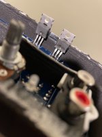
I got to the transistors and it looks like they sanded the markings off so I can't read what they are using. Sneaky...
Attachments
Last edited:
- Home
- Amplifiers
- Class D
- Class D Amplifier Output