Hello everyone,
I'm new at class D, but I've made a simple circuit in LTSpice using a gate driver IC, this IC is said to be shoot through free, but I think my circuit is having this problem, because dissipation is very high and even without any input signal (input shorted to ground), there is dissipation in the output devices, why this happens?
Another problem that I have is related to DC instabilities, because the output voltage oscillates near 0V at a frequency near to the one of the reference triangle (500 kHz), to prevent this from happen I've added a huge filter at the output but this measure kills the high frequency response.
Talking about the oscillations at low frequencies, this amplifier was first tested with a single ended configuration, but when I changed the design to H bridge (with two amplifiers with oposite input signal phase) low frequency oscillations (near 4kHz) appear in the outputs of both amps and with exactly the same phase, the current that crosses the load seems to be a little unstable but near 0 without input signal, with input signal the amplifier works normally, can you help me here.
PS:
Circuits attached
I'm a newbie, I don't know how to calculate the poles and zeros of the circuit (to get the frequency response of the amp), maybe the problem lies there.
Best regards,
Daniel Almeida
Attachments
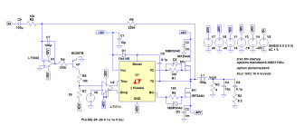

You have exceeded the supply voltage of the LTC4444. It cannot be used with voltage levels you are applying to Vcc and GND (>22v). Spice models can behave rather funny if PS limits are exceeded or they can work but the real circuit will be an epic failure. Read the datasheet again and understand the supply limits of the parts. This part may not be intended for this application. D1 should be a different diode. See datasheet.
Thank you for your help,
I've reduced the supply voltage of the LTC4444 IC to -28V (Vcc), maintaining -40V in ground, but the problem remains, and now I have much more distortion, what are the best diodes for the the boost circuit? I know that this IC is not very good for class D amps, but I'm trying to understand more about class d using "discrete" parts, not a class D chipamp or a class D controller, do you know any good gate driver IC to replace LTC4444, if so, where I can get the models?
Best regards,
Daniel
Gate drivers? Int. Rect. and Intersil for a start. See hip4081/4080. See IRS20957. Most will not have spice models.
I have a lot of experience using spice and do not take the models at face value. Many of the more complex ICs, like gate drivers and complete class d amplifiers have spice models that may or may not model the completely accurate behavior of the IC. If you find models at all you are lucky. All of spice modeling is an approximation of how the circuit will/may perform. Especially in the non-linear regions of operation. Spice is a good tool but there is no replacement for a REAL breadboard. And this goes for all class d amplifier circuit design.
I have a lot of experience using spice and do not take the models at face value. Many of the more complex ICs, like gate drivers and complete class d amplifiers have spice models that may or may not model the completely accurate behavior of the IC. If you find models at all you are lucky. All of spice modeling is an approximation of how the circuit will/may perform. Especially in the non-linear regions of operation. Spice is a good tool but there is no replacement for a REAL breadboard. And this goes for all class d amplifier circuit design.
I appreciate your help,
Do you know which "discrete" componentes should be used to make a class D amplifier that could realy work in real life?
Generally in the simples designs (that I don't know if they work), there's na opamap working as integrator and connected to the main feedback loop in inverting configuration, a comparator, na oscillator, a shot through protected gate driver IC with boost, a pair of N-channel MOSFETs, and an output filter consisting of a series inductor and a shunt capacitor. The problem is the supply voltage of the driver generally is low (12-15V), and the comparator is for 3-6V, some kind of level shifter is required between the input circuit and the comparator.
PS:
As single IC circuits it's better to use something like TDA8954, or something like IRS2092?
Best regards,
Daniel
I appreciate your help,
Do you know which "discrete" componentes should be used to make a class D amplifier that could realy work in real life?
Generally in the simples designs (that I don't know if they work), there's na opamap working as integrator and connected to the main feedback loop in inverting configuration, a comparator, na oscillator, a shot through protected gate driver IC with boost, a pair of N-channel MOSFETs, and an output filter consisting of a series inductor and a shunt capacitor. The problem is the supply voltage of the driver generally is low (12-15V), and the comparator is for 3-6V, some kind of level shifter is required between the input circuit and the comparator.
PS:
As single IC circuits it's better to use something like TDA8954, or something like IRS2092?
Best regards,
Daniel
it is quite simple: your output filter with 150uH/10uF exhibits a self resonance close to 4kHz
Yes it's a possible, I will make a few more tests with different (smaller) values for the inductor and capacitor.
Thanks for your help
Thanks for your help
Hello everyone,
Another problem that I have is related to DC instabilities, because the output voltage oscillates near 0V at a frequency near to the one of the reference triangle (500 kHz), to prevent this from happen I've added a huge filter at the output but this measure kills the high frequency response.
input signal the amplifier works normally, can you help me here.
Best regards,
Daniel Almeida
There will always be some residual carrier on the output.
I have seen this on numerous class d amps.
Its well outside audio range so not really a big problem.
It will radiate a little because of this.
500KHz is quite fast so you might get hot mosfets.
I usually use 250KHz.
- Status
- Not open for further replies.
- Home
- Amplifiers
- Class D
- Class D amp with self oscillations at low frequencies?