Hello,
Are there any other simulations of a class D amplifier other than this on the www?
Why high voltage supply rail for class D amplifier?
Are there any other simulations of a class D amplifier other than this on the www?
Why high voltage supply rail for class D amplifier?
Hello,
Are there any other simulations of a class D amplifier other than this on the www?
Why high voltage supply rail for class D amplifier?
Besides looking for simulations in the www, it is really worth to play with simulation on your own computer.
...just saw that you posted the same topic in three threads...
Well the reason to chose a certain rail voltage is to allow a certain max unclipped output voltage.
Usually it is not optimal to adjust the output voltage by the filter, because this implies that you will get massive changes in the output voltage depending on the signal frequency. Reasonable filters allow less than 2db change between 20Hz and 20kHz.
Adjustment of the output level usually is derived by adjusting the modulation level.
Do you want to share a certain clue behind your approach?
Or are you just asking?
i hear you say output voltage but its the current in the speaker that counts....whether your rail voltage is low or high, you can still get equally high current in the speaker.....just see the simulations......
so why go for a high rail voltage?
so why go for a high rail voltage?
It seems like you are not targeting a HiFi application.
If you just want to produce a beep at a certain frequency, then you can of course generate high currents (and voltages as well) by a tuned resonance cricuit - by the expense of comparably high current stress in the entire load circuit.
But note, if you just want a beep (alarm signal application ?), then it would be by far more efficient to run the full bridge with the desired beep frequency and just feed that rectangle into the filter.
By using proper snubber caps on the switches, correct dead time and an optimized resonant circuit you can achieve ZVS and avoid switching losses.
eem2am!
It's quite unpolite to refer to a file which is not accessible without registering to a different forum.
And even if you attached here, don't expect others to use the same simulator as you!
You should show a format which is accessible for everybody. A picture for example.
And the real question seems to be: what you've been misunderstood? (Or not understood at all.)
No need for simulation for this kind of very basic and simple question. If you need simulator for this, then you need to learn basic electrotechnics first. And then you won't need to ask something like this.
Sorry!
Thanks Pafi, I will get a picture uploaded....that i can manage.
I dont think edaboard.com forum is a competitor to diyaudio forum though, since this is a specialist audio site, so i doubt diyaudio staff will be concerned.
I am pretty sure that LTspice is the most advanced SMPS simulator of the free simulators available......it certainly can include the most nodes.
When designing an smps, or class D amp, its just standard procedure to get a representative simulation going so that i can check my calculated values using the simulator.....this is just being sensible.
No doubt if you have got money you may be using a much better simulator, maybe not....maybe if you have money you will want to use a simulator for smps which is made by one of the best simulation engineers on the planet (Mike Engelhardt of linear.com)
Hi Pafi,
eem2am had posted the files also here, but in another thread.
http://www.diyaudio.com/forums/class-d/210810-why-high-voltage-rails-class-d-amp.html
Kind of annoying attitude to start three threads for the same topic....
@eem2am:
LT Spice is definitely a very good simulator for switching applications - not just among the free simulators.
Still wondering if you are going for hifi or beep.
If not beep, but hifi:
Most loudspeakers are designed for voltage drive from a low impedance voltage source (Key words: Damping, transfer function). Most woofers will generate a massive booming at their resonance, when driven from a current source.
Further have a look for basic design considerations of the output filter. There were some nice threads around recently.
OK thanks Chocoholic, ill do that.
...that thread i post many places because that way many other beginners will benefit from the simulation of the class d amp.......it is the only basic simulation of a class d amp anywhere on the www.
Though in extra reply to Pafi, i tell that most designers are mentally compromised as myself.....and need simulations to get our thick heads into the job at hand.
Maybe you dont believe that most designers are mentally challenged like me?......well in that case, to you i will give proof!!.............i was recently working at a billion dollar global company who has a power supply dept............................400 $10 million dollar prototype units went unstable because the smps designer implemented a control loop which was pitiful.
i soon will post you his output of his 300w full bridge smps.....you will laugh.,,,and you will realise that most designers are thickeys like me.
oh and BTW i do not do just beep...i do for electric guitar
......................................
ok, so here is the output stage of the 220w full bridge with vin = 48v, vout = 29v, fsw = 300khz.
http://i40.tinypic.com/2h7f4p1.jpg
.....notice how ridiculous it is?
......look at where the bulk capacitance is.......AFTER the emc inductor, and with a 220mR resistor in series with the 68uF electrolytic.
Yes, this power supply oscillated like crazy when we changed from a fairchild CNY17-3 opto to a CNY17-3 opto by vishay..(ie same part just diofferent manufacturer)
When the load was added to this output, (the load had a 400uf cap in front of it, this made the resonent freq of the output emc filter go less than three times the crossover freq of the smps and it oscillated like crazy)
yes several million pounds wasted there.
Now do you beleive that there is a shortage of smps engineers and that most are mentally challenged individuals like me?
....i did not design this output stage by the way.........i told the designer i thought it was wrong, and he replied to me "proove it"..........so i wrote to a pal at a semiconductor company......that "pal" then against my wishes, saw how bad it was and went to the overall head of engineering of this big company......i tell you my name was mud for inadvertently going over my bosses heads even though it was not me...it was my "pal" from the semiconductor company.
Ok now we have straightened that most engineers are mentally challenged individuals like myself who need simple simulations to get there heads round a circuit before designing it...................may i re-ask my initial question....
Please does any person know if there is a simple class d simulation anywhere on the www (preferably in ltspice)
Last edited:
Everybody make mistakes. I do it many times also. But ignorance different from accident! Simulator prevents the expert form accidents, but cannot replace knowledge. If you can't interprete the results correctly, then the simulator is harmful, not helpful, because prevents using your brain.
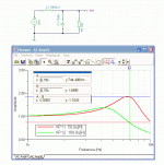
I attached a picture to show what happens at different frequencies, if you choose the wrong inductor. It boosts the output at a frequency, but is this what you wanted to achieve? I quess not.
Or do you really ask why to use high supply voltage? You must have heard about Ohm's low!
Actually not. It can be stable. It depends on the details of the feedback, what is not on the picture.
Please OFF your own topic, if you wish!
+ I think pushing PrintScreen is easier than suffering from limited attachment size, and expect others to use the same simulator as you. And much more polite!
I attached a picture to show what happens at different frequencies, if you choose the wrong inductor. It boosts the output at a frequency, but is this what you wanted to achieve? I quess not.
Or do you really ask why to use high supply voltage? You must have heard about Ohm's low!
..notice how ridiculous it is?
Actually not. It can be stable. It depends on the details of the feedback, what is not on the picture.
Please OFF your own topic, if you wish!
+ I think pushing PrintScreen is easier than suffering from limited attachment size, and expect others to use the same simulator as you. And much more polite!
Attachments
Last edited:
Regarding the erroneous smps feedback loop....
Yes i appreciate it could be stable......"could".
.....but you would need to do state space analysis in order to proove stability of that kind of network.
The rest of the feedback is the standard TL431/Opto.
If you want to use the standard equations as of basso book or standard poles and zeros then you need to have your majority capacitance on the feedback node.
...sorry i cannot paste more as its confidential to the company.
...I dont know of any free simualators as good as ltspice so i presume most are using ltspice if they use a free one.....i wish other semiconductor companies did the same but they dont.
regarding the class d :-
i know Ohms law, but if you look at my sims, they both use Ohms law, and both can do the job, so why is the high voltage one better?
both can do the job, so why is the high voltage one better?
In your simulations the high voltage one is not necessarily better. Both suffer from the same problem: the frequency response of the amplifier is not flat and is severely load dependent in the audio band (remember that at the resonant frequency of the filter the output impedance of the amplifier is very large). If you are not using post-filter feedback, the only way to mitigate this is to place the poles of the output filter above the audio band. You'll want to do this even if you use feedback, since the full-power bandwidth of the amplifier is determined by the cut-off frequency of the output filter.
Last edited:
Nothing wrong with the topology. I've worked on designs done the same way. You *can* simulate this kind of supply - only thing is your pole/zero plot just gets a bit more complex when you take the complex load into consideration. It just becomes more of a MATLAB exercise than a pen/paper exercise.http://i40.tinypic.com/2h7f4p1.jpg
.....notice how ridiculous it is?
......look at where the bulk capacitance is.......AFTER the emc inductor, and with a 220mR resistor in series with the 68uF electrolytic.
Yes, this power supply oscillated like crazy when we changed from a fairchild CNY17-3 opto to a CNY17-3 opto by vishay..(ie same part just diofferent manufacturer)
In this case, they just designed the compensation wrong. If an op-amp change threw the thing into oscillation, I'm sure it had major problems before - and standard line/load/"switched resistor in the feedback divider" testing would have shown something was extremely wrong.
I'm guessing this thing was a brick of some sort?
That's simply not true unless you only want to play one note (or "beep" as Chocoholic put it).....whether your rail voltage is low or high, you can still get equally high current in the speaker.....
I wish I could. You still haven't posted pictures of either the circuit or the results......just see the simulations......
You mean aside from the simulations I posted in this thread here on diyAudio last week?.......it is the only basic simulation of a class d amp anywhere on the www.
No, I consider that an insult to "most designers".Maybe you dont believe that most designers are mentally challenged like me?......
Guitars can play more than one note. Maybe you should check in your simulator if your amp can do that too.oh and BTW i do not do just beep...i do for electric guitar
Thank you!+ I think pushing PrintScreen is easier than suffering from limited attachment size, and expect others to use the same simulator as you. And much more polite!

Last edited:
eem2am!
Back to the elementary school: 100 W on 8 ohm is 40V amplitude. It's not a mistery from VDD=40V. The question is: why did you get only 100 W from VDD=80V? Because you used too high inductance, or limited the modulation depth, etc...
Everything can be ruined, it's not the fault of the high power supply voltage! Vdd=80 V is enough for almost 400 W @ 8 ohms with the proper filter, at the appropriate freq, this is why normal engineers prefer higher voltage.
So the real question is not why do engineers use high supply voltage, but how to correctly design an amplifier.
And how to attach a screenshot. 😡
And how to post everything in ONE topic. 😡
thanks, critisisms appreciated.... of course everything is relative, when i say "mentally challenged", i mean in comparison with brilliant genius's.
I come from an era when computers didnt exist, except in secret underground government laboratories...i struggle with IT.
I come from an era when computers didnt exist, except in secret underground government laboratories...i struggle with IT.
OK, this is completely ridiculous!
I was bored enough to register on the other forum and download the files so I could see what the OP was up to.
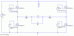
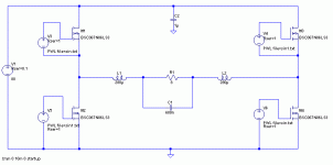
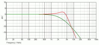
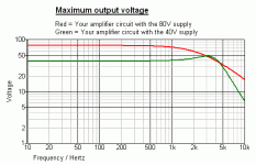
The two amps have totally different output filters, with the one running off the 80V supply being 6dB down at 4KHz, compared to the one running off the 40V supply. Since he only tested at 4KHz, the maximum output is the same for both. Duh!
In case anybody else wants to have a look, the attached zip file contains a folder with the four files the OP posted. The MOSFETs used don't seem to be in the standard LTSpice library so to run the sims I substituted IRF240, which seemed to work well enough.
Attachments
Thanks Godfrey,
Maybe those mosfets are only lately included and the current download has them, previous not...because i found them in standard lib.
I intend to make a test signal containing more frequencies.......my point is that, as you have shown, the same power (100w in this case) can be gotten from 80v and 40v rails, so why is 80v better?...or is it not better?
If you use the same filter on both amps, the one with an 80V supply will give 4 times as much output power as the one with a 40V supply.
Try putting the same capacitor and inductors that you use in the 40V amp into the 80V amp and you'll see what I mean. Suddenly you will have nearly 400W at 4KHz.
The only reason you got the same power is because the filter on the output of the amp with the 80V supply is throwing away most of the output at 4KHz.
The graph below shows the maximum output voltage for your two circuits. Yes, it is almost the same at 4KHz but so what? Look at the rest of the audio band.
Attachments
Thanks Godfrey,
Maybe those mosfets are only lately included and the current download has them, previous not...because i found them in standard lib.
I intend to make a test signal containing more frequencies.......my point is that, as you have shown, the same power (100w in this case) can be gotten from 80v and 40v rails, so why is 80v better?...or is it not better?
Lots of reasons to run higher rail voltages than theoretically necessary:
- To make room for Rds(on) loss, output filter resistance, power supply ripple/sag, etc.
- To maintain a minimum switching frequency in a self-oscillating design.
- To ensure minimum on-times of FETs in a fixed frequency design.
- For clipping protection, it's better to have an overdriven amp go into current/voltage/thermal limiting than clip and potentially destroy speakers.
- Besides, you need higher rails to make room for current sensing loss, and to create some room between the maximum operating point and protection point of the amplifier to avoid false protection trips.
And there's really only one reason not to run higher rails - increased switching loss.
- Status
- Not open for further replies.
- Home
- Amplifiers
- Class D
- Class D amp simulations?
