Hi fellow diyaudiomembers,
I'm developing a class D amp for an resonant power supply.
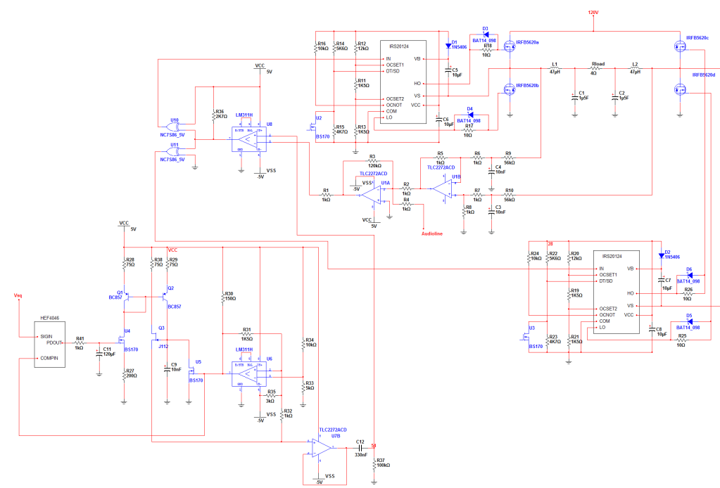
The amp is an 1500W single supplied by 120 Vdc Class D subwoofer.
Here you fokes have a schedule:

I'm trying to find the errors.
Since I'm new to the class D techniques, I fail finding the errors.
Would you fokes give it a try?
Speccs:
Switching frequency = 65KHz till 200KHz
Audio frequency = 10 till 200 Hz
I'm aiming for 90% efficiency and low THD (0.3% even 01.% odd)
I'm developing a class D amp for an resonant power supply.
The amp is an 1500W single supplied by 120 Vdc Class D subwoofer.
Here you fokes have a schedule:
I'm trying to find the errors.
Since I'm new to the class D techniques, I fail finding the errors.
Would you fokes give it a try?
Speccs:
Switching frequency = 65KHz till 200KHz
Audio frequency = 10 till 200 Hz
I'm aiming for 90% efficiency and low THD (0.3% even 01.% odd)
200KHz is a too high frequency to audio of 200KHz. You can improve the efficiency reducing such a frequency. 10KhHz is sufficient, and you must need so less current to drive power mosfet´s. I made a prototype several mouths ago, I used 250KHz but full range 20-20000Hz, and sounds very fine. By the way, what errors do you find? Eventually you can simplify the sawtooth / triangle wave generator
200KHz is a too high frequency to audio of 200KHz. You can improve the efficiency reducing such a frequency. 10KhHz is sufficient, and you must need so less current to drive power mosfet´s. I made a prototype several mouths ago, I used 250KHz but full range 20-20000Hz, and sounds very fine. By the way, what errors do you find? Eventually you can simplify the sawtooth / triangle wave generator
The switching frequency is unadjustable since it is the switching frequency of the powersupply which is used to switch the PowerFETs. I wouldn't know how to make that sawtooth any easier with the same lineairity.
The switching frequency will be around 100K for about 85-90% of the loads. Resonant powersupplies adjust their switching frequency to the loads. A higher load means a lower switching frequency.
My mainerror seems to be in my control circuit (feedback) and seems to have something to do with the gain I give the feedback before it's summed together with my audioline.
200KHz is fine for such an amp if uses FDP2532 orIRFx4228. Tough IRS20124 might not be able to drive properly the current chosen MOS-FET's without buffering. If will decrease the switching frequency then the output filter inductors will get much bigger, and the switching losses saved at the power stage will move to conduction and core losses in inductors.
Capacitor C12 from triangle generator seems huge, and its value will give you a very low triangle amplitude. try a 100nF or up to 470nF. I haven't look at the feedback loop or anything else yet.
Capacitor C12 from triangle generator seems huge, and its value will give you a very low triangle amplitude. try a 100nF or up to 470nF. I haven't look at the feedback loop or anything else yet.
I know the principle of resonant power supplies, in fact I did one with L6565 and works properly. The question would be if the amplifier uses the same frequency as PS, a sub/multiple of it, or is independent and synchronized with it?
I suggest I simplest triangle wave geneartor I used with hit.
Divide the input frequency by two (74HC74 or HCF4013). Then, the outputs will be capacitively coupled to a double input integrator (It is difficult to explain, but I´ll try).
From Q out, a big cap (.01uf, series integration resistor to + of an opamp of high slew rate (TL072 or better), since this point to AGND via an integrating cap.
From -Q of FF, same circuit, but integrator cap tied to opamp out. Adjust both input integrating caps and R´s (same value same function) to obtain a perfect triangle wave of f/2 input at the FF.
I did it with HCF4013 and 1/4 TS274 and the output is very good at 250KHz and with an amplitude of 8VPP with +-6V power supply, and very low power consumption..
Finally, as pwm frequency is frequency modulated, surely you couldn´t listen AM radios in this amp, interference will be very big.
Best regards.
I know the principle of resonant power supplies, in fact I did one with L6565 and works properly. The question would be if the amplifier uses the same frequency as PS, a sub/multiple of it, or is independent and synchronized with it?
I suggest I simplest triangle wave geneartor I used with hit.
Divide the input frequency by two (74HC74 or HCF4013). Then, the outputs will be capacitively coupled to a double input integrator (It is difficult to explain, but I´ll try).
From Q out, a big cap (.01uf, series integration resistor to + of an opamp of high slew rate (TL072 or better), since this point to AGND via an integrating cap.
From -Q of FF, same circuit, but integrator cap tied to opamp out. Adjust both input integrating caps and R´s (same value same function) to obtain a perfect triangle wave of f/2 input at the FF.
I did it with HCF4013 and 1/4 TS274 and the output is very good at 250KHz and with an amplitude of 8VPP with +-6V power supply, and very low power consumption..
Finally, as pwm frequency is frequency modulated, surely you couldn´t listen AM radios in this amp, interference will be very big.
Best regards.
I just tested a lookalike of your theory of the triangle, it's less lineair than mine, while being a bit more expensive, the only advantage your schedule has is powerefficiency.
My powersupply is synch'ed with my class D, and is independent. The Vsq in my schedule is the squarevoltage created by the switching stage of the power supply.
200KHz is fine for such an amp if uses FDP2532 orIRFx4228. Tough IRS20124 might not be able to drive properly the current chosen MOS-FET's without buffering. If will decrease the switching frequency then the output filter inductors will get much bigger, and the switching losses saved at the power stage will move to conduction and core losses in inductors.
Capacitor C12 from triangle generator seems huge, and its value will give you a very low triangle amplitude. try a 100nF or up to 470nF. I haven't look at the feedback loop or anything else yet.
You're absolutely right about Capacitor C12 from triangle generator, I adjusted that immediatly. Which of the drivers you named would you recommend? Or would you just take other Powerfets for lower gatecharges?
... so the frequency of the power stage isn´t constant, and then triangle frequency and amplitude aren´t also constant??My powersupply is synch'ed with my class D, and is independent. The Vsq in my schedule is the squarevoltage created by the switching stage of the power supply.
I don´t like this scheme.
There are several issues with that design:
1. The global loop seems positive, not negative feedback
2. The loop gain is low, consider increasing R3 or adding a series capacitor
3. 1N4148 is only 100V, will fail short destroying drivers and fets. What do you supply drivers with? 12V? 15V?
Overally I like the idea of PLL'ing the SMPS for the main clock, it can reduce supply current ripple and get rid of beating. However if you use LLC halfbridge the PLL may be not needed, the duty cycle is already 50%, so just triangulating (integrating) the SMPS clock may be enough.
Last edited:
There are several issues with that design:
1. The global loop seems positive, not negative feedback
2. The loop gain is low, consider increasing R3 or adding a series capacitor
3. 1N4148 is only 100V, will fail short destroying drivers and fets. What do you supply drivers with? 12V? 15V?
Overally I like the idea of PLL'ing the SMPS for the main clock, it can reduce supply current ripple and get rid of beating. However if you use LLC halfbridge the PLL may be not needed, the duty cycle is already 50%, so just triangulating (integrating) the SMPS clock may be enough.
1. Adjusting global loop (at least trying to find a way to)
2. Increased R3 for higher gain, Didn't use the capacitor, cause the would cause another 90 degrees phaseshift to the feedback loop. Which would mean 2x 90 degrees = an oscillator
3. Driver supply = 15V, I entered that diode a bit to fast since I mostly use that one for my designs.
I can't use a halfbridge configuration because of the high power + current
120V/4ohm = 30A
1500W/120V = 12.5A
As far as I know an halfbridge would give me complex thermal problems.
This system could be seen as a complicated way of integrating the SMPS signal. Just using an intergrator would give a way higher non-lineairity and amplitude variation. This system does not have the high effeciency but is exacter in many ways.
Last edited:
... so the frequency of the power stage isn´t constant, and then triangle frequency and amplitude aren´t also constant??
I don´t like this scheme.
The frequency is not constant, but the amplitude of the sawtooth is.
I'm using the PD of the PLL + a LFP to generate a DC voltage. That goes to the mosfet --> the higher that voltage the higher the current through my currentmirror. The higher that current the faster the capacitorload increases.
I'm using a hysteresis controlled comparator to make a threshhold for that voltage. For example --> if triangle is (higher than) 3V, the output becomes high. Which will of course trigger the fet and cut of the voltageload of the capacitor. Causing the capacitor to unload at a high speed. So basicly this is an Voltage Controlled Sawtooth Oscillator with an PLL system at the entrance. The PLL uses the output voltage of the comparator as comparement to the entrance voltage. The difference is the output of the PD, which will go through the LPF and generate that DC voltage for the entrance of the fet.
'LLC halfbridge' is a SMPS topology I suppose you are using
I am using an LLC SMPS but this system need to work for fullbridge as well.
Sorry for the misunderstanding, english is not my native language.
- Status
- Not open for further replies.
- Home
- Amplifiers
- Class D
- Class D Amp problems