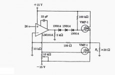
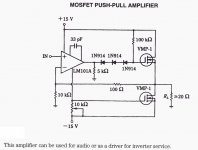
Problem is there are no pin numbers on the op-amp, the LM101A looks to have 3 balance/compensation pins - without pin numbers you are just guessing connections - it seems like an unusual circuit.
The TL072 (and many other) op-amps would not work, as they don't have the extra pins. The TL071 has offset pins but they are different connections to the 3 compensation/balance pins of the LM101A. The LM101 (and LM201 and LM301) look unique on the pinout and are still available.
The TL072 (and many other) op-amps would not work, as they don't have the extra pins. The TL071 has offset pins but they are different connections to the 3 compensation/balance pins of the LM101A. The LM101 (and LM201 and LM301) look unique on the pinout and are still available.
Last edited:
The 5k load resistor forces current through the -ve supply on negative signal swings, modulating the lower FET's gate - its probably acting as an asymmetric class B, or as a class A with current load that's somewhat active to reduce dissipation. Depends on the quiescent supply current the setting of the 10k preset and the gate voltage curve of the FET.
Presumably this circuit is an adaptation to the lack of complementary output devices.
Presumably this circuit is an adaptation to the lack of complementary output devices.
Ohh, I must have been squinting when I looked at that first time, I missed the -15V label and thought the "jump" on the wire was a junction....
Would likely work with any op-amp then, unless the 33pf compensation capacitor on the op-amp is critical for stability.
Would likely work with any op-amp then, unless the 33pf compensation capacitor on the op-amp is critical for stability.
A '101 with a 30pFd cap is a '741, THE first "good" (for the time) chip opamp. Any similarly slow opamp will work similarly.
The 5k on the chip output and the 10k pot on the lower Gate are a Quasi-Complementary drive. Sketch the opamp's output stage to see this.
The 100 Ohms is almost certainly a typo for 100k. (100r is unity gain, huge input drive. 100k gives gain of 11 which is appropriate for 13V peak output and 1.2V peak input.
The LM101 1N914 and VMP-1 mark this as a VERY old design. 1967-1977?
Many thanks, yes, I was baffled by the 100 ohm, so posted it.A '101 with a 30pFd cap is a '741, THE first "good" (for the time) chip opamp. Any similarly slow opamp will work similarly.
The 5k on the chip output and the 10k pot on the lower Gate are a Quasi-Complementary drive. Sketch the opamp's output stage to see this.
The 100 Ohms is almost certainly a typo for 100k. (100r is unity gain, huge input drive. 100k gives gain of 11 which is appropriate for 13V peak output and 1.2V peak input.
The LM101 1N914 and VMP-1 mark this as a VERY old design. 1967-1977?
The schematic drawing style looks very similar to the ones in early editions of Millman & Hayes, this came from online search using keywords Class B MOSFET amp, I found the original full image scrolling little in the image search results, it's here
Attachments
- Home
- Amplifiers
- Solid State
- Class B?