Hi ! Can I increase the quiss current for this Class B amp into Class AB , would that improve the sound? , or anything at all ? or not if there is no cross-over distortion to begin with ?.
It's a Toshiba SC-M15 , Input and pre-driver stages are in Class A, output in Class B; both stages are fed from two different trafo windings.
I was thinking : Changing R653 with a bigger value pot might do it . Run it at 50 - 70 mA , maybe more , thermally I don't think it would be a problem , the whole case it's a heatsink, ( Q613 , Q615 , might need heatsinking ? )
Why did they bias it into Class B and not Class AB in the first place !?.
- Bruno.
Attachments
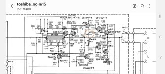

It doesn't look like you'd run out of heatsink because of that but unless it immediately sounds or measures way better I'd shy away from that one. If you go for it you might at least be careful not to let it run away before you know it's stable. It looks like they have 16mA on them, which might not be very class B for smaller transistors.
Last edited:
The SM appears to be poorly written. I believe the amp is biased into AB, albeit lightly. Note in page 6 schematic of the manual, there is 3.6mV across R645 and R647, corresponding to about 16.4mA idle bias in the output transistors.
Referring to the "Idle Power Adjustment" on page 5, maybe the verbiage suggesting 1 to 2 mV could be construed to be accuracy re the 3.6mV nominal indicated on the schematic? The 16mA idle current is smaller than the "Oliver" target which would suggest about 26mV across the emitter resistor, but the D607 temperature compensation isn't very sophisticated. Perhaps that prompts Toshiba's conservative bias.
Referring to the "Idle Power Adjustment" on page 5, maybe the verbiage suggesting 1 to 2 mV could be construed to be accuracy re the 3.6mV nominal indicated on the schematic? The 16mA idle current is smaller than the "Oliver" target which would suggest about 26mV across the emitter resistor, but the D607 temperature compensation isn't very sophisticated. Perhaps that prompts Toshiba's conservative bias.