Hi All,
Ever since joining this forum class B auto-bias has been on my mind. Thanks to Russel Kinder's RK-Auto200 design.
Russel helped me along massively in solid state design when I was a newbie here. Only at the time I couldn't make sense of his autobias schemes.
Yesterday I think I finally conjured up a circuit that does the job correctly.
I set out to find a circuit that:
https://www.diyaudio.com/community/threads/rk-auto200w-amplifer.367674/
who got the framework from Wlliam Chater:
https://www.diyaudio.com/community/...ontrol-for-power-amplifiers-revisited.367386/
The Framework:
Sensor Circuit -> Peak Detector -> Integrator -> Bias generator
What really cracked my brain was howto detect the bias current under large signal conditions.
It is known that the class B signal currents cross at the bias current. So some circuit should measure what current is present when I(R24)=I(R23).
I guess this is what is referred to as "Zero Crossing Detection".

Yesterdays contraption seems to pull it off:

Two current mirrors Q37 to Q42 forming the sensor circuit sense the bias current through 0.22ohm Rsense.
The top mirror subtracts I(Rsense)*Constant from I(J3) while the bottom mirror adds I(Rsense)*Constant to I(J3). This constant is set by by Re and Rsense. The output currents of the two mirrors are added onto Rc to create voltage V(Rc) which is proportional to bias current (and signal current).
Current mirror output currents Ic(37) & Ic(q38) summed to I(Rc) creating V(Rc):

Now under class B signal conditions the magnitude of the V(Rc) peaks are proportional to the bias current. (some kind of personal revelation to me🤣)
This is where the peak detector comes in. I've tried single and dual opamp active peak detectors, all left some artifacts in the FFT. Passive does not. So I Simply implemented it with D11 and C11 to create V(vpeak):

Next V(vpeak) is fed to an integrator (U4 TL072) that compares it to reference voltage Vset. In this case -4V, being the target voltage for Vpeak.
Now the bias current can be defined by Rsense, Re, Rc and Vset. Rsense Re and Rc set the gain of the current mirror sensor circuit, the integrator should make all the rest irrelevant.
The integrator then drives an opto-coupler to engage the bias-spreader. More opto-current results in more bias and no opto-current results in no bias. This should be true even when the output stage is getting boiling hot.
Now the loop is complete and it seems to be pretty sturdy but I'd like to make it sturdier. Unfortunately the bias does drop (10mA or so) when a 100W 20Hz signal kicks in. It never quite gets back to where it was but at least we see integrator trying to bring it back up:

Then there is the issue of loop stability. Depending on the Gain of the sensor circuit, the integrator time constant and C11 (probably many more), very low frequency oscillation may occur. Its damped ok now but id like to know howto properly compensate it. I haven't figured out howto do proper stability analysis on this.
The integrator output current in response to large Low F signal:

The output current dropping indicates the integrator thinks the bias has gone up so it drops and we loose some bias. It seems to still misinterpret large signals for bias fluctuations but only a little bit. The loss of some bias current I attribute to the non-perfect Sensor circuit and the passive peak detector. Perhaps there are other causes. Perhaps it needs one more op-amp after all. Perhaps this is accurate enough. Most important is that the bias doesn't keep falling or shoot up like many of my other tries. Neither does it leave anything sign of existence in FFT's.
Hopefully I can breadboard this in the following days. I'll probably waste more time simulating and considering:
I'd love to hear your thoughts,
Cheers
Ruben
Ever since joining this forum class B auto-bias has been on my mind. Thanks to Russel Kinder's RK-Auto200 design.
Russel helped me along massively in solid state design when I was a newbie here. Only at the time I couldn't make sense of his autobias schemes.
Yesterday I think I finally conjured up a circuit that does the job correctly.
I set out to find a circuit that:
- Replaces thermal tracking. Forming a subsonic bias feedback loop that compensates for thermal drift.
- Maintains the bias current even with full power 20 Hz signals.
- Should bring the bias up, such that before the bias feedback starts acting there is no bias current and all remains safe.
- Leaves no signs of its presence opposed to a passively biased output stage.
https://www.diyaudio.com/community/threads/rk-auto200w-amplifer.367674/
who got the framework from Wlliam Chater:
https://www.diyaudio.com/community/...ontrol-for-power-amplifiers-revisited.367386/
The Framework:
Sensor Circuit -> Peak Detector -> Integrator -> Bias generator
What really cracked my brain was howto detect the bias current under large signal conditions.
It is known that the class B signal currents cross at the bias current. So some circuit should measure what current is present when I(R24)=I(R23).
I guess this is what is referred to as "Zero Crossing Detection".
Yesterdays contraption seems to pull it off:
Two current mirrors Q37 to Q42 forming the sensor circuit sense the bias current through 0.22ohm Rsense.
The top mirror subtracts I(Rsense)*Constant from I(J3) while the bottom mirror adds I(Rsense)*Constant to I(J3). This constant is set by by Re and Rsense. The output currents of the two mirrors are added onto Rc to create voltage V(Rc) which is proportional to bias current (and signal current).
Current mirror output currents Ic(37) & Ic(q38) summed to I(Rc) creating V(Rc):
Now under class B signal conditions the magnitude of the V(Rc) peaks are proportional to the bias current. (some kind of personal revelation to me🤣)
This is where the peak detector comes in. I've tried single and dual opamp active peak detectors, all left some artifacts in the FFT. Passive does not. So I Simply implemented it with D11 and C11 to create V(vpeak):
Next V(vpeak) is fed to an integrator (U4 TL072) that compares it to reference voltage Vset. In this case -4V, being the target voltage for Vpeak.
Now the bias current can be defined by Rsense, Re, Rc and Vset. Rsense Re and Rc set the gain of the current mirror sensor circuit, the integrator should make all the rest irrelevant.
The integrator then drives an opto-coupler to engage the bias-spreader. More opto-current results in more bias and no opto-current results in no bias. This should be true even when the output stage is getting boiling hot.
Now the loop is complete and it seems to be pretty sturdy but I'd like to make it sturdier. Unfortunately the bias does drop (10mA or so) when a 100W 20Hz signal kicks in. It never quite gets back to where it was but at least we see integrator trying to bring it back up:
Then there is the issue of loop stability. Depending on the Gain of the sensor circuit, the integrator time constant and C11 (probably many more), very low frequency oscillation may occur. Its damped ok now but id like to know howto properly compensate it. I haven't figured out howto do proper stability analysis on this.
The integrator output current in response to large Low F signal:
The output current dropping indicates the integrator thinks the bias has gone up so it drops and we loose some bias. It seems to still misinterpret large signals for bias fluctuations but only a little bit. The loss of some bias current I attribute to the non-perfect Sensor circuit and the passive peak detector. Perhaps there are other causes. Perhaps it needs one more op-amp after all. Perhaps this is accurate enough. Most important is that the bias doesn't keep falling or shoot up like many of my other tries. Neither does it leave anything sign of existence in FFT's.
Hopefully I can breadboard this in the following days. I'll probably waste more time simulating and considering:
- Sensing from the Emitter resistors opposed from collector resistors and making the circuit float with the output.
- Eliminate the opto-coupler and use Q19 and Q20 current sources to control the bias.
- A transistor based Integrator
I'd love to hear your thoughts,
Cheers
Ruben
Last edited:

Eventually, you're going to have to measure the amplifier's performance using test equipment and a variety of output loads.
Since it's inevitable, since you KNOW it's inevitable: why not do it right now? You may discover that (the real amplifier in the real world with real parasitics and real imperfect-matching-of-parts), behaves somewhat differently than the chalkboard; differently than the circuit simulations. If you find problems: change the design and seek a fix! If you find no problems whatsoever: congratulations, YER DONE!
Let the amplifier tell you what's perfect and what needs modification. Unlike armchair professors of circuit design, the amplifier is never wrong and the amplifier doesn't disregard second order effects because they're too messy to analyze easily. Build the amp, measure the amp, and tweak the amp until it gives the measurements you are seeking.
Including measurements of stability / avoidance of oscillation. Square wave response, overshoot, clipping entry and clipping exit. Long speaker cables. Ribbon speaker loads. Do your worst and let the amplifier do its best.
To be fair, a 100W 20kHz signal is not a typical audio signal, so that's a pretty harsh test for your circuit. I think you may need a resistor in parallel with C11 to set a discharge time constant for the peak detector. Maybe that might alter the behaivour you're seeing?
Since it's inevitable, since you KNOW it's inevitable: why not do it right now?
Ah yes indeed. You're right. Lets jump to the breadboard. I believe you told me these things before in a reply on another thread. All true but nothing of what youre saying is news to me. Thanks anyhow.
Cheers Mark Johnson!
KapitiaAudio Thank you. Indeed we'll need a resistor there. This however makes the bias drop more under signal. Even with 50Mega//C11 the drift increases by 10%. Perhaps an Opamp peak detecter can offer remedy. Back to the chalkboard.
The current through the diode is very peaky. With 50Mega//C11 these peaks start to show. At -150dB which should be deep into the noise floor.
With R//C11

Without R//C11

The current through the diode is very peaky. With 50Mega//C11 these peaks start to show. At -150dB which should be deep into the noise floor.
With R//C11
Without R//C11
You need to add something to predictably discharge C11. As the voltage across it needs to go negative, a parallel resistor won't do, but a resistor to a negative supply will. The resulting error can be compensated for by also adding a diode and resistor on the other side, right after the setpoint voltage source.
You can also try compensate for the internal differential resistance of the Q23Q24 transistors; to do this, add resistors with a nominal value of approximately 10-20 ohms between the Q23 collector and resistor R50 and the Q24 collector and resistor R61.As always,
I'd love to hear your thoughts,

The feedback loop will be hard to stabilize with two poles. I would start with one. Replace C14 with a resistor, leaving C11 as the only pole.KapitiaAudio Thank you. Indeed we'll need a resistor there. This however makes the bias drop more under signal. Even with 50Mega//C11 the drift increases by 10%. Perhaps an Opamp peak detecter can offer remedy. Back to the chalkboard.
I believe the reason why slow auto-bias is not commonly used is because the bias will drop with signal, especially at high frequencies. If you can solve that, you will have made a genuine breakthrough.
Ed
Dear Ed that's interesting. at high frequencies it seems more stable. Although I only ran 100+ second simulations at 20Hz.
ill have to leave it running at 2kHz or so and come back in an hour to see how it did.
Yes the devil is in startup behavior. At startup the integrator output goes up before Vpeak even dropped below 0V so it thinks it is overbiased and the bias goes through the roof. I think the input to the integrator has to be able to move faster than the output of the integrator. Changing C11 to a reasonable 100nF fixes this but does allow more crap to make it to the output and distortion goes up. Albeit from 0.06ppm to 0.23ppm 100W 20Hz. In my opinion 0.23ppm at 20Hz is crap. 100dB of loopgain should really make it 0ppm.
Moving the poles apart will make the loop stable, but to function as a peak detector, C11 and its resistor must have a long time constant. That leads to instability when combined with C14's long time constant.Rupopulles said:I think the input to the integrator has to be able to move faster than the output of the integrator. Changing C11 to a reasonable 100nF fixes this but does allow more crap to make it to the output and distortion goes up.
The solution is to make C11 work as both the peak detector and integrator. The loop then has one pole and is guaranteed to be stable.
Ed
like this:
View attachment 1286294
You need to add something to predictably discharge C11. As the voltage across it needs to go negative, a parallel resistor won't do, but a resistor to a negative supply will. The resulting error can be compensated for by also adding a diode and resistor on the other side, right after the setpoint voltage source.
Thank you for the excellent suggestions. Ill give these tricks a try
Alright this is much better already. Thanks again for the suggestions. Rsense is now 0.1ohm. For no particular reason I flipped the thing so now we have a dip detector of a different kind. I hoped this different kind would introduce less noise and it does indeed.
Dip-Detect Auto-Bias has have a ring to it.
The biasloop is stable, startup is clean. FFT is clean. It does loose a bit more bias with large low F signals. Almost 30mA actually. But im happy. The FFT is cleaner eventhough bias is lower. The amplifier hosting this bias system is much better at correcting crossover distortion than it is at correcting tiny diode switching transients it seems.
I tried passive current mirrors in the sensor current and noticed this makes the bias drop more. Hinting that the sensor circuit could be the culprit here(or atleast one of). Next i'll try implementing opamp current mirrors to eliminate its inaccuracy.

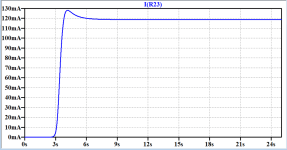
V(dip) here corresponding to the 'registered' bias current shows the response nicely. I(R21) is emitter current of one of the output BJT's also shows how the bias appears about 3 seconds after startup:

Much Cheers,
Ruben
Dip-Detect Auto-Bias has have a ring to it.
The biasloop is stable, startup is clean. FFT is clean. It does loose a bit more bias with large low F signals. Almost 30mA actually. But im happy. The FFT is cleaner eventhough bias is lower. The amplifier hosting this bias system is much better at correcting crossover distortion than it is at correcting tiny diode switching transients it seems.
I tried passive current mirrors in the sensor current and noticed this makes the bias drop more. Hinting that the sensor circuit could be the culprit here(or atleast one of). Next i'll try implementing opamp current mirrors to eliminate its inaccuracy.
V(dip) here corresponding to the 'registered' bias current shows the response nicely. I(R21) is emitter current of one of the output BJT's also shows how the bias appears about 3 seconds after startup:
Much Cheers,
Ruben
Attachments
Last edited:
It is known that the class B signal currents cross at the bias current.
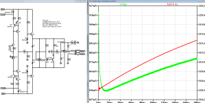
Turns out this is not actually true at high frequencies. Here a passive bias spreader is used (with increased temperature coefficient). DC bias setting is 103mA but crossover occurs at 75mA. DC Bias is NOT crossing current? Nevertheless it could still be an adequate approximation for this circuit to function.
As a result the sensor circuit registers a drop in bias and the integrator tries to bring up the crossing current. After not too long it stops rising so thats a relief: Again Vdip corresponds to registered bias current, Ix is the output current of the integrator. (more current is more bias)
Trying to reduce the low frequency 'bias loss' I tweaked the resistor and cap values a bit. The diodes can be replaced with matched dual bjt's. This halved the bias loss to 15mA. Trying opamp current mirrors for the sensor circuit did not yield improvements.
I made a little note on the schematic of things to check at each iteration. Am I missing something major?
Good to mention is that when all pre-driver, driver and output bjts are set to 100deg C the bias only goes up 1mA or so. It seems it'll correct for temperature drift indeed. Of course only the IRL bench can confirm.
Much thanks and cheers
Ruben
Attachments
Last edited:
Yes. You need to learn how to design a stable feedback loop.Rupopulles said:Am I missing something major?
The three poles associated with C11, C12, and C13 will not be stable.
Use one pole (C12). Replace C13 with a resistor. Get rid of C11. A one-pole loop will not show ringing or oscillation.
Ed
Dear Ed,
I hope youre not saying I havent learned howto make a stable feedback loop. Because you'd be quite wrong.
what youre reffering to as ringing is the 20Khz signal that made it through the low pass filters.
It might look like three poles but the noninverting integrator has one pole. Its transfer function is 1st order only. C11 is not dominant. Its time constant is much lower. I can assure you its stable. I cant show you with bode plots yet. Working on it.
My trouble is where to place the small signal voltage source for bode analysis. Then I could prove its stable. This is not as obvious to me as with a power amp.
Caterpillar or motorboating is what happens when it goes unstable. Its very obvious. Note the timescales.
I appologize. Now I see my post isnt clear at all.
Much Cheers
Bob Cordell's "Oscillation Sniffer" from his Designing Audio Power Amplifiers textbook, might be useful. Bob presents it in chapter 23 ("Other Amplifier Tests") of the 1st edition, dunno what chapter number that becomes in the 2nd edition.
Okay. I agree that the non-inverting integrator makes the loop stable. I see that the time constant of C11 is small.
Part of the difficulty is that the schematic is hard to read. 😉
The system is non-linear, and so applying linear analysis will be an approximation at best, or at worst completely wrong.
My apologies. You understand your design better than I do. 🙂
Ed
Part of the difficulty is that the schematic is hard to read. 😉
The system is non-linear, and so applying linear analysis will be an approximation at best, or at worst completely wrong.
My apologies. You understand your design better than I do. 🙂
Ed
- Home
- Amplifiers
- Solid State
- Class-B Output Stage Auto-Bias. No funny business. Just replacing thermal tracking. Please evaluate this approach