Stefanoo said:
He suggests to use as much feedback as you can!
Good.
Stefanoo said:
.......magazines consider high feedback is bad...
Just voodoo magazine nonsense.
Tube_Dude said:
The one with heavy feedback will sound the same (accurate ), as the input signal source (no more ,no less ).
The other with no feedback , will sound "romantic", self effacing and "nicer" than the source signal...
The choice is your's...")

st r said:Usually feedback amps have open loop gain which is very variable with frequency (to achieve stability), and since feedback is the more effective the more gain you have, this means that in certain regions of the spectrum the residual error and all the effects of feedback will be higher than in other regions. Feedback also needs very good circuit layout to avoid feedthrough, parasitic oscillations or (even worse) behaviors at the edge of instability, all frequency-dependent so that sound is affected in unpredictable ways. Moreover, you should dimension things so that in all circumstances you will never go anywhere near to clipping, which is much nastier in fed-back circuits (is this term OK? I have invented it right now).
I am not an expert, but I suspect that if people knew how to use feedback it would not have got its bad fame. As a matter of fact, who knows how many audiophile records have been recorded through tens (100's) of operational amplifier circuits, each with its own feedback, but seriously designed so that professionals could use them reliably.
--st.r.

Re: Re: Class B - high feedback

The reverse is true.
Miles Prower said:
The most common abuse of NFB is using it to cover for a fundamentally bad open loop design.
Miles Prower said:
A MOSFET based design can't tolerate quite so much NFB
The reverse is true.
lineup said:
But what I try to avoid is MAXIMAL open loop gain.
This is wrong, whichever way you slice it.

Miles Prower said:Since the MOSFET has a wicked crossover characteristic, keep it out of Class AB operation, or at least don't push it too far into AB.
Actually, what you want to do is keep your MOSFET SEPP output stage out of Self's ''optimal'' class-B, and bias it into class-AB.
The later gives NO crossover distortion; viz. class-AB SEPP output stage designs cannot, by definition, suffer from crossover distortion-at all.
Moreover, gain-step distortion due to class-AB operation is an order of magnitude less than that of a BJT SEPP output stage, since Gm in the former is an order of magnitude less than that of the later.
This, however, is moot, as the lower Gm ensures that the MOSFET SEPP stage generates roughly an order of magnitude greater distortion that the BJT stage anyway.
mikeks said:
No-voltage amplifier with voltage feedback.
Darkfenriz is right , in open loop conditions the amp is a transconductance amplifier.
The output is the drains of the Mosfets, which represent a not so perfect current source.
In this particular case , we even have a local feedback loop from the source 0,22 Ohms resistor to the TL072 inverting input . this is a form of feedback depending in the current in the load , increasing even more the open loop output impedance...
So we end in open loop conditions with ... voltage in , current out.
Only the global negative feedback turn this amp in a voltage amplifier...
This design's output stage is merely an elaboration of the so-called complementary feedback pair with less than 100% local feedback, due to R28/60.
Thus, when the major loop, constituted in part by R59/52, is disabled, the output stage remains resolutely voltage-out-for-voltage-in: a voltage amplifier with gain.
Note that the op. amp. IC7 acts as a near-ideal complementary common emitter stage.
Thus, when the major loop, constituted in part by R59/52, is disabled, the output stage remains resolutely voltage-out-for-voltage-in: a voltage amplifier with gain.
Note that the op. amp. IC7 acts as a near-ideal complementary common emitter stage.
darkfenriz said:Classic Sziklai CFP is also transconductance stage with negative feedback, isn't it?
No

johndiy said:can you please tell me whats important class or specs
Sound is important. Class and specs are just tools.
Nelson Pass said:
Sound is important. Class and specs are just tools.
One of the best posts I've seen!
darkfenriz said:If you want such a discussion, Mike
Some actually miss the vigilant, Victorian English stuffed, posts of Mikek now and then.

I take it there is no point in cross-sectoral separation of output stage NFB ?
i was talking with a friend of mine that is more experienced than i am related those things.....He said when looking this thread
"There are certainly reasons for dislike
as well as for to love any person lived or living.
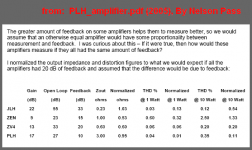
Work done investigating and publishing figures like this
is one of the reasons I love The One and Only.
( wont tell you why I hate the man )
note:
These figures are from some wellknown Class A ampifliers
as this is what 'PLH_amplifier.pdf' is all about.
But illustrates how very different amplifiers can be
and still be having a good sound and be loved by listeners.
"There are certainly reasons for dislike
as well as for to love any person lived or living.
Work done investigating and publishing figures like this
is one of the reasons I love The One and Only.
( wont tell you why I hate the man
)note:
These figures are from some wellknown Class A ampifliers
as this is what 'PLH_amplifier.pdf' is all about.
But illustrates how very different amplifiers can be
and still be having a good sound and be loved by listeners.
Attachments
- Status
- This old topic is closed. If you want to reopen this topic, contact a moderator using the "Report Post" button.
- Home
- Amplifiers
- Solid State
- Class B - high feedback