Douglas Self and Bob Cordell have shown lower value emitter degeneration resistors in Class-AB output stages reduces crossover distortion with less higher order harmonics making crossover distortion less audible.
Can we get rid of emitter degeneration resistors in Class-AB output stages? No, not in the standard Class-AB Darlington configuration with typical rail voltages of 40-80 volts. Why? Bob Cordell shows in his book that higher rail voltages require higher value emitter resistor to stop local thermal runaway.
But with Current Source Driven output transistors it is possible to get rid of emitter degeneration resistors in Class-AB output stages and still have thermal stability.
The method for this thread is current driven power transistors with the Class-AB current splitting done in small-signal isothermal transistors isolated from the power transistor heatsink. Details to follow.
Comments, questions, suggestions, etc, are all very welcome. Thanks in advance 🙂

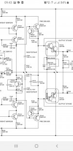
This circuit shows the basic current source driven output stage

Small-signal transistors Q3,Q4 do the current splitting for Class-AB. Q5,Q6 are cascodes to keep the voltage low to the splitter transistors and they do not use any emitter degeneration. Power transistors Q1,Q2 are current driven an therefore do not need emitter degeneration resistors to stop thermal runaway. Q7,Q8 are thermally linked to Q3,Q4 respectively to track ambient temperature changes. Local feedback is applied to the inverting input (emitters of Q3,Q4). With R3 of 0.22 ohms and an 8 ohm load the voltage gain is 33 (31dB) and with an idle current of 200mA the THD is 1.5% at 80W near clip and 0.6% at 1W. Idle current is trimmable with I1 and I2. The attached sim files can show it is stable with changing temperature.


At 1W (right) the distortion is mainly 3rd harmonic and the higher harmonics fall away very rapidly, so fast that we only hear the 3rd harmonic if it is more than about 0.1%. So adding 20dB more feedback will make crossover distortion inaudible for typical music and speech material. This can be achieved using an opamp since the drive voltage for full output is only 1V peak.

THD with this circuit is 0.0015% at 80W into 8 ohms. Compensation is required using C3 and R7 with C4 and small signal bandwidth is 800kHz. E1 can be an inverting opamp with a gain of 0.1. It only needs to supply 2mA peak at 20kHz. It is used for neutralization of the Miller feedback capacitance of the power transistors to allow faster removal of charge during high slew rates (since no base-emitter resistors are necessary for current drive of the power transistors).
Small-signal transistors Q3,Q4 do the current splitting for Class-AB. Q5,Q6 are cascodes to keep the voltage low to the splitter transistors and they do not use any emitter degeneration. Power transistors Q1,Q2 are current driven an therefore do not need emitter degeneration resistors to stop thermal runaway. Q7,Q8 are thermally linked to Q3,Q4 respectively to track ambient temperature changes. Local feedback is applied to the inverting input (emitters of Q3,Q4). With R3 of 0.22 ohms and an 8 ohm load the voltage gain is 33 (31dB) and with an idle current of 200mA the THD is 1.5% at 80W near clip and 0.6% at 1W. Idle current is trimmable with I1 and I2. The attached sim files can show it is stable with changing temperature.
At 1W (right) the distortion is mainly 3rd harmonic and the higher harmonics fall away very rapidly, so fast that we only hear the 3rd harmonic if it is more than about 0.1%. So adding 20dB more feedback will make crossover distortion inaudible for typical music and speech material. This can be achieved using an opamp since the drive voltage for full output is only 1V peak.
THD with this circuit is 0.0015% at 80W into 8 ohms. Compensation is required using C3 and R7 with C4 and small signal bandwidth is 800kHz. E1 can be an inverting opamp with a gain of 0.1. It only needs to supply 2mA peak at 20kHz. It is used for neutralization of the Miller feedback capacitance of the power transistors to allow faster removal of charge during high slew rates (since no base-emitter resistors are necessary for current drive of the power transistors).
Attachments
Last edited:
Ian, interesting setup! I remember a very old Wireless World article where the output stage was also current driven, but the current was used to switch the polarity of the drive to either the pos or the neg part of the output.
So that was pure class B. I can't remember the author, I thought it might be Sandman.
I guess your setup is also basically class B?
Edit: it was Peter Blomley.
Jan
So that was pure class B. I can't remember the author, I thought it might be Sandman.
I guess your setup is also basically class B?
Edit: it was Peter Blomley.
Jan
Attachments
Last edited:
Hi Jan,
Was it the Blomley article Fig 1 (pt1) here https://keith-snook.info/wireless-world-magazine/Wireless-World-1971/New Approach to class-B Amplifier Design by P Blomley.pdf. Fig 6 he proposes diodes with current drive and Fig 7 either bipolars or FETs as common base. But his final circuit Fig 1 (Pt2) used bipolars common-base under current drive. Notice one Si (D4) and one Ge (D5) diode for a modicum of voltage bias voltage presumably for less crossover distortion at the higher frequencies where there is less feedback.
For this post I and doing the splitting with voltage drive and the splitter transistor current drives the power transistors and that's where the current drive is used and the idle current is fairly stable with power transistor junction temperature. I am not aiming for accurate Class-B. I am operating in Class-AB with next to no emitter degeneration in the splitter transistors, just some internal ohmic resistances in the emitter and base. Then I am slightly underbiasing for a curving upward smooth curving wingspread plot for minimal high order harmonics.
@ Dave. Thanks
Last edited:
I've done such simulations a while ago in my QSC-Kenwood l-01A itterations where i simply removed by mistake the BE resistor of the final transistors or q5, q6
collector resistors seeing abnormally low THD , then removed the emitter resistors too, lowering the thd even more, but I wouldn't trust it in real life more than using single transistor darlingtons.While not exactly identical instance I saw enough 55MHz darlington transistors fried in modern multichannel sony and pioneers or old Sanyo and Hitachi amps to become a believer of the cause.
Besides every 3ef class ab output stage is actually a current driven stage once you go past the first predriver of the 3ef.
I'd say this is how safe current drive looks like in Arcam A/P85 amps and they still don't do away with emitter resistors and thermal compensation, on the contrary!
If I'm going to put Kenwood's l-01A 0.47 ohms emitter resistor and older qsc 0.47 ohm emitter resistors against more modern qsc 0.22 ohms emitter resistor trading safety for more power and less thd into 2 ohms near clipping , I'll instinctively choose the older versions of QSC that barely had any decent heatsink yet worked for decades with 0.47 ohms resistors.
Fundamently any final transistor in a 2ef or 3ef configuration is purely current driven near clipping and about 90...95% of the output signal excursion down to crossover area no matter the configuration.If it wouldn't be current driven what would the global voltage feedback network do?
Attachments

Last edited:
Yes Peter Blomley. He uses 'emitter resistors' on his Locanthi T's but they are not in the output circuit so do not give rise to unwanted cutoff of the idle half of the output.
I think your implementation is better, but my old brain always pulls up old stuff and then can't remember where or by whom ;-)
Jan
I think your implementation is better, but my old brain always pulls up old stuff and then can't remember where or by whom ;-)
Jan
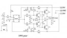
As a student I assembled this one in 1991, you have a very similar design.Comments, questions, suggestions, etc, are all very welcome. Thanks in advance 🙂
Attachments
It is easy to get rid of emitter resistors using the Shiklai triple, or rather, the combination of Shiklai and Darlington.Can we get rid of emitter degeneration resistors in Class-AB output stages? No, not in the standard Class-AB Darlington configuration with typical rail voltages of 40-80 volts. Why? Bob Cordell shows in his book that higher rail voltages require higher value emitter resistor to stop local thermal runaway.
such a cascade seems to be the first applied by Othalla.
There were countless small amplifiers in the 70's working that way...but would you use it on a few thousand bucks speaker?As a student I assembled this one in 1991, you have a very similar design.
Hi Jan,
More on the "underbiasing for a curving upward smooth curving wingspread plot for minimal high order harmonics".
Look at the wingspread plot before applying the local feedback below

This is generated by connecting the load direct to common and leave the inverting input 'open' (actually goes to common via the 0.22 ohm).
Notice the gain plot d(Vout) increases by a factor of about 4 at the peaks. This is due to the reduced bias and not using emitter degeneration in the splitter stage. To put this into perspective the plot below shows a standard Class-AB stage with emitter resistors and varying bias:

The region I am operating in (arrows) has a width of +/-120mV of input signal which is about 4*Vt (thermal voltage). This curve is chosen because it has a smooth transition in gain and therefore the higher order harmonics are minimised.
Notice a higher bias gives less gain change but there are faster wobbles giving more 5th, 7th, 9th harmonics. And a lower bias than what I suggest leads to a mid gain requiring more feedback to suppress the 3rd harmonic.
BTW with no emitter degeneration there is more gain available so it does not need much extra global feedback to make the 3rd harmonic inaudible even at full output power.
More on the "underbiasing for a curving upward smooth curving wingspread plot for minimal high order harmonics".
Look at the wingspread plot before applying the local feedback below
This is generated by connecting the load direct to common and leave the inverting input 'open' (actually goes to common via the 0.22 ohm).
Notice the gain plot d(Vout) increases by a factor of about 4 at the peaks. This is due to the reduced bias and not using emitter degeneration in the splitter stage. To put this into perspective the plot below shows a standard Class-AB stage with emitter resistors and varying bias:
The region I am operating in (arrows) has a width of +/-120mV of input signal which is about 4*Vt (thermal voltage). This curve is chosen because it has a smooth transition in gain and therefore the higher order harmonics are minimised.
Notice a higher bias gives less gain change but there are faster wobbles giving more 5th, 7th, 9th harmonics. And a lower bias than what I suggest leads to a mid gain requiring more feedback to suppress the 3rd harmonic.
BTW with no emitter degeneration there is more gain available so it does not need much extra global feedback to make the 3rd harmonic inaudible even at full output power.
Fascinating! You should have been born 50 years earlier - you would have cornered the HiFi amplifier market!
Jan
Jan
Hennady Kovalsky said:
As a student I assembled this one in 1991, you have a very similar design.
The first I noticed was the PE/PW Texan (https://www.angelfire.com/sd/paulkemble/sound8h.html). I have seen similar from Russia on diyAudio (by OldDIY) eg from 1991Post 9 dreamth said:
There were countless small amplifiers in the 70's working that way...but would you use it on a few thousand bucks speaker?
@ dreamth in Post 5 you appear to be removing the emitter degeneration resistors in the standard type Darlington output stage. I absolutely don't recommend doing this in the standard Darlington topology. My topology is completely different the standard type Darlington output stage, my topology allows direct current drive to each of the power transistors when base-emitter resistors are NOT used.
Hi Jan,Fascinating! You should have been born 50 years earlier - you would have cornered the HiFi amplifier market!
Jan
You are so kind. Much appreciated!
I didn't quite understand the question...There were countless small amplifiers in the 70's working that way...but would you use it on a few thousand bucks speaker?
what does the cost of the speaker system matter if there is protection for 10 bucks.
Last edited:
ALL QSC amps and Kenwood l01A output stages are Sziklai connected...but darlington transistors do current drive as well.I have several topics with simulations and discussions around Patt Quilter's topologies and the beneffit of drawing the final stage as in Kenwood l01A version and believe me, no simulaion has shawn me the results of a faster base emitter discharge yet it certainly is benefficial.I'd go anytime with the higher thd than just risk putting my speakers on fire.@ dreamth in Post 5 you appear to be removing the emitter degeneration resistors in the standard type Darlington output stage. I absolutely don't recommend doing this in the standard Darlington topology. My topology is completely different the standard type Darlington output stage, my topology allows direct current drive to each of the power transistors when base-emitter resistors are NOT used.
Actually your topic around bloomley topology made me take a step further on this path of reducing thd, but bloomley is class B which is thermally safer than a class AB.
You quoted me in russian...I didn't quite understand the question...
what does the cost of the speaker system matter if there is protection for 10 bucks.
Very interesting design Ian! Thanks for sharing!
How come there’s no risk of thermal runaway when the output transistors are current driven? The data sheet for MJL3281 shows an increasing hFE with temperature. Isn’t this a problem?
edit: I guess the increase of hFE with temperature is too low for runaway?
How come there’s no risk of thermal runaway when the output transistors are current driven? The data sheet for MJL3281 shows an increasing hFE with temperature. Isn’t this a problem?
edit: I guess the increase of hFE with temperature is too low for runaway?
Last edited:
Hi Ian,This circuit shows the basic current source driven output stage
View attachment 1083398
Small-signal transistors Q3,Q4 do the current splitting for Class-AB. Q5,Q6 are cascodes to keep the voltage low to the splitter transistors and they do not use any emitter degeneration. Power transistors Q1,Q2 are current driven an therefore do not need emitter degeneration resistors to stop thermal runaway. Q7,Q8 are thermally linked to Q3,Q4 respectively to track ambient temperature changes. Local feedback is applied to the inverting input (emitters of Q3,Q4). With R3 of 0.22 ohms and an 8 ohm load the voltage gain is 33 (31dB) and with an idle current of 200mA the THD is 1.5% at 80W near clip and 0.6% at 1W. Idle current is trimmable with I1 and I2. The attached sim files can show it is stable with changing temperature.
View attachment 1083400 View attachment 1083401
At 1W (right) the distortion is mainly 3rd harmonic and the higher harmonics fall away very rapidly, so fast that we only hear the 3rd harmonic if it is more than about 0.1%. So adding 20dB more feedback will make crossover distortion inaudible for typical music and speech material. This can be achieved using an opamp since the drive voltage for full output is only 1V peak.
View attachment 1083404
THD with this circuit is 0.0015% at 80W into 8 ohms. Compensation is required using C3 and R7 with C4 and small signal bandwidth is 800kHz. E1 can be an inverting opamp with a gain of 0.1. It only needs to supply 2mA peak at 20kHz. It is used for neutralization of the Miller feedback capacitance of the power transistors to allow faster removal of charge during high slew rates (since no base-emitter resistors are necessary for current drive of the power transistors).
Do I see it correctly, local NFB network uses very low value resistors and it will consume a half ouput power?
You used dadod for FFT liles??
I like your approach and new ideas, as always very interesting.
BR Damir
- Home
- Amplifiers
- Solid State
- Class-AB with no emitter resistors and good thermal stability and good sound