Not sure what you mean. Quiescent current setting or power output maximum setting?
The power output is set by the amount of drive and the available voltage. In this configuration, the output stage will do its best to deliver what has been asked.
If you mean quiescent current, adjusting the bias on Q2 will set the current and therefore the power sat across the output transistors.
In Class AB the quiescent current is fairly low.
I want to adjust the bias of transistors with these resistors but i dont know how can i choose the proper value of them.Not sure what you mean. Quiescent current setting or power output maximum setting?
The power output is set by the amount of drive and the available voltage. In this configuration, the output stage will do its best to deliver what has been asked.
If you mean quiescent current, adjusting the bias on Q2 will set the current and therefore the power sat across the output transistors.
In Class AB the quiescent current is fairly low.
Your plan will not make large power output.
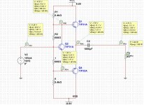
Forget bias (deal with bias later). Try to drive a 4 Ohm load as near as possible to your +9V supply. The only thing which can do this is the 8.4k resistor. Idle it passes 1mA, but the current will reduce as base voltage approaches +9V. With base near +4.5V you have only 0.5mA available. What is the hFE of a TIP31? Say 100? Then the maximum output current is 100*0.5mA or 50mA. So 4V swing at the output can support at-most 50mA, which is an 80 Ohm load, not 4 Ohm.
Conversely we can divide 8.4k by hFE and say the transistor acts-like a 84 Ohm source. So working into 4 Ohms it can swing at-most 4/(84+4) or 0.045 of the 9V supply, 0.41V peak.
Look at other proven audio amplifier plans and work out why they did it that way.
Idle Bias: Q2 runs the 1mA passed by the 8.4k resistors. The base resistors make double Vbe. Since Q2 is same-size as Q1 Q4, we can estimate that 2*Vbe of Q2 will cause 1mA in each of Q1 Q4. However transistor matching is inexact. (Also we have seen that the 1mA in the bias resistors will NOT swing the load at full power.) In Practice you will NEED emitter resistors on Q1 Q4 to absorb small difference in Vbe, and you typically want to trim for the actual parts in hand.
If your signal source will drive 8 ohm loads, it is possible enough drive can be delivered to the output transistors through the 600 ohm resistors. 5v/600ohm=8 ma base drive, * hfe of output transistors, 20 maybe, 160 ma out. Into 4 ohms that would be 100 mwatt.
But if you had an 8 ohm driving source, why would you need this circuit at all?
For the absolute simplest circuits, search for 3 transistor amps, djoffe posted one and there have been others. For 20-70 w class AB you need 6 transistors, IMHO. AX6, TGM8, Basic 50, see this thread for simple early circuits: A collection of vintage, single supply, low to medium power amplifiers for Daniel
My load must be 4 ohm and i need to see 10w average at the output. Also i must use split split supply +-9v. Resistors are not correct to do it
> My load must be 4 ohm and i need to see 10w average at the output.
Use a chip.
Power Amp design is non-trivial. Chips do what they say. There is much choice at this power level. China-market kits can be cheaper than buying parts for a discrete amp.
Use a chip.
Power Amp design is non-trivial. Chips do what they say. There is much choice at this power level. China-market kits can be cheaper than buying parts for a discrete amp.
Two questions:
1. why post this in the Power Supplies section?
2. how many marks do you get for this homework assignment?
1. why post this in the Power Supplies section?
2. how many marks do you get for this homework assignment?
- Status
- Not open for further replies.
- Home
- Amplifiers
- Power Supplies
- Class AB audio amplifier