Dear Gents,
What is the maximum power I can obtain from a class AB amplifier using a 50-0-50/6Amps transformer ?
Can anyone suggest (with PCB layout and schematic) better class AB amplifier?
I want to make use of below main components
Transformer 28-0-28/ 8Amps & 50-0-50/6 Amps
MJL4281 x 5
MJL4302 x 5
C5200 X 4
A1943 X 4
2N3773 X 10
Thanks in advance
Edison C.
Dear Gents,
What is the maximum power I can obtain from a class AB amplifier using a 50-0-50/6Amps transformer ?
As a rule of thumb, half of the VA of the transformer, although technically it can be equal to the VA but not advisable
Last edited:
Thanks Scott,
So , considering 2 channels ~ (112+ 112 watts) & (150+150 watts) . Right?
Any suggestions on amplifier ?
(I went through several posts and confused to chose right one matching with my components.)
So , considering 2 channels ~ (112+ 112 watts) & (150+150 watts) . Right?
Any suggestions on amplifier ?
(I went through several posts and confused to chose right one matching with my components.)
50-0-50Vac @ 6Aac is 600VA
That is good for approximately 300W to 600W of total maximum output power.
You can go outside these limits, it will still work.
50-0-50Vac will give supply rails of approximately +-75Vdc
Expect the maximum output of the amplifier to be approximately 8V to 15V below the quiescent supply rail voltage.
That +-75Vdc could give a maximum output of 68Vpk to 60Vpk.
For those limits the maximum power into 8r0 would be from 289W to 225W
and into 4r0 would be from 578W to 450W
and into 2r0 would be from 1156W to 900W
You pick the numbers you like and watch it blow up.
Last edited:
Minimum DC - with risk of shock
Dears,
What is the minimum DC voltage/current that can cause risk of shock?
Dears,
What is the minimum DC voltage/current that can cause risk of shock?
Regarding current, a few milliamperes are already quite unpleasant and anything over 30 mA can kill you if it flows such that some of it goes through your heart. The current path from one hand to the other is notorious.
Regarding voltage, officially 42 V is the highest voltage still considered safe (at least according to the regulations that apply in the Netherlands, but they are probably copied from an international standard). The real answer is current times skin resistance. For a given voltage, you run much less risk with a dry skin than with sweat all over your body.
Rails of +/- 75 V, so 150 V between the rails, are definitely dangerous, especially in a hot country like India.
Last edited:
I used to work for British Telecom, the old strowger exchanges were 50V dc, huge copper busbars everywhere, it was considered safe so long as you didn't wear jewellry haha.
SARA-2016
@ alex mm/ greierasul ,
Dears,
Thanks for such a wonderful pcb layout. Unfortunately, drivers transistors are not available here and for import, shipping seems to be expensive.
Any replacements for A1381,C3503C
Regards,
@ alex mm/ greierasul ,
Dears,
Thanks for such a wonderful pcb layout. Unfortunately, drivers transistors are not available here and for import, shipping seems to be expensive.
Any replacements for A1381,C3503C
Regards,
Here's an easy idea. Use the 50-0-50 as two 50 Vac supplies. Rectify each separately to about 72 Vdc single rails. This will give you about 60 W in 8 ohms per amplifier, and you essentially have a dual-mono amplifier. You can easily put it onto 4 ohms to get somewhere around 110 W. Just select the correct number of output transistors per amplifier.
The amplifier I would build would be a simple one using the single rail, and I would use MJE340/50 for the VAS and drivers, and TIP35/6C for the outputs. They are robust, and I have never had quality issues using these transistors.
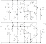
Now, I know I'll get flak for posting a schematic with an output capacitor, but hey, it does work. And importantly, you can bridge this amplifier quite simply, and then you will get a good 230 W, and you can do away with the capacitors. The advantage is that you can still use the low-voltage transistors, which are easy to come by.
The schematics shown are a starting point, not a final design. For one thing, there aren't enough output transistors. I would use at least two pairs per amplifier.
The amplifier I would build would be a simple one using the single rail, and I would use MJE340/50 for the VAS and drivers, and TIP35/6C for the outputs. They are robust, and I have never had quality issues using these transistors.
Now, I know I'll get flak for posting a schematic with an output capacitor, but hey, it does work. And importantly, you can bridge this amplifier quite simply, and then you will get a good 230 W, and you can do away with the capacitors. The advantage is that you can still use the low-voltage transistors, which are easy to come by.
The schematics shown are a starting point, not a final design. For one thing, there aren't enough output transistors. I would use at least two pairs per amplifier.
Attachments

Are you seriously suggesting someone use TIP35/36C transistors as output transistors on +/-75V rails? Yeah... watch them explode...
Also MJE340/350 are RUBBISH drivers. Use BD139/140 if you must use a TO-126 device. MJE243/253 are better.. Even better on a large amp are TO-220 packages such as MJE15032/3.
Given where you are in the world, are you sure those MJL4281, MJL4302, A1943, C5200 are even genuine ? Take pictures of them.
Given where you are in the world, are you sure those MJL4281, MJL4302, A1943, C5200 are even genuine ? Take pictures of them.
No, absolutely don't use TIP35/6C on +-75V. Check the post and schematic - it's a single 75 (72) V supply. Same as +-37 V. That's the idea because TIP35/6C are very available.
MJE340/50 have worked well for me. Not that highly recommended, but again, they're very available and I would definitely not go so far as to call them rubbish. Have you used them? I prefer them to BD139/140 anyway.
2SC5200 and 2SA1943 are very much back in the game. ST and Fairchild (ON Semi) both make nice versions, Fairchild make a 17A version. Just buy from an approved retailer, and those are listed on ST or Fairchild's sites. They aren't the best, but they're cheap.
I don't recommend 2SA1943/2SC5200 for +-75 V, btw. You need too many of them in the output. 250 W devices will be far more suitable.
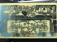
PCB ready
Dears,
I have the PCB ready.
What is the maximum output power that can be obtained from this amplifier?
What should be the current for maximum power?
What should be the PCB copper thickness? (mine is with 1OZ copper)
What is the optimal bias current?
Here is my PCB.
Regards,
Dears,
I have the PCB ready.
What is the maximum output power that can be obtained from this amplifier?
What should be the current for maximum power?
What should be the PCB copper thickness? (mine is with 1OZ copper)
What is the optimal bias current?
Here is my PCB.
Regards,
Attachments
- Status
- Not open for further replies.
- Home
- Amplifiers
- Solid State
- Class AB Amplifier