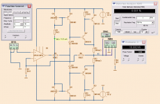
Your "perfesser" is an idiot. This is absolutely hideous! Here's a design I did for the audio strip for a longwave receiver. You can see here how to do a power amp design right. This particular final is just what you want: it's push-pull, and it's Class AB. Unlike that monstrosity your "perfesser" suggested, it sounds quite good, despite the fact that I wasn't designing for Hi-Fi, as this is a communications receiver, where fidelity is not necessary, and where it's not possible with a DBM anyway. 99.9% of longwave work is done in CW anyway, so it doesn't matter.
The course isn't actually about any of this (yet this project is 1/4 of our grade) it is mostly and supposed to be about logic gate construction and covers DTL, TTL, CMOS, RTL and some other things like electron drift/ hole mobility, doping levels etc...etc...
Things like amplifiers and audio filters are never covered, the instructor was in a band however so he has a thing for audio.
Here's some reviews:
Herb Detloff
Herb Detloff
Herb Detloff
Herb Detloff
There are tons of those. It really is a shame because every other teacher I've had in the department has been exceptional.
Anyways thats the end of my rant, it doesn't deserve to be in here as it is.
I would also question why it needs to be inverting too. The input impedance is set by the 1K resistor which is way to low for a normal audio amp. Also the low frequency response is determined by the combination of C2 and R223 which form a high pass filter.
That was his decision too, I previously had a 100k and 1Meg.
That design is a very simplistic opamp in itself, with the ability to drive the output directly. I does suffer from higher input bias requirements (lower input impedance) than an actual opamp. Some form of differential input is quite common as it provides really convenient nodes for input and feedback and helps reduce dependance on individual device characteristics. There is nothing special about the transistors I've shown, a few general purpose small signal devices and a pair of mid-power drivers and your choice of outputs. You could use your TIP31/32 for drivers and 2N3055/2955 for outputs if you like, they are cheap and readily available. Some resistor values have to be adjusted for significantly different supply voltages if the same quiescent currents are to be maintained, but the design is simple and solid.
Thanks, this makes a lot of sense.
I really appreciate all the help everyone has given. I certainly feed I have a better understanding of the subject if anything else.
Here, try this.
I've numbered the components for ease of discussion.
Class AB and good enough for 8-10W of power and with a decent general pupose unity gain stable op-amp the power bandwidth will be about 40KHz.
with a bit of optimization you should easily be able to get <0.2% distortion.
Use a TL071 - unity gain stable op-amp.
Good luck
Thanks for the sketch. I'll try this next if my current device doesn't meet specifications.
I mentioned in post #12 the technique of using a resistor to help overcome the dead band (crossover region).
I actually cobbled your circuit together on a breadboard and find that for low impedance loads and even with a 4560 opamp the results are not good. I used some crusty old outputs that would be similar to the TIP31/32 type.
The problems are... the opamp has insufficient current drive when faced with low gain transistors and a low impedance load.
I tried the text book diode bias arrangement using 0.22 ohm emitter resistors for a little stability. Much better but this showed another issue. The resistor/diode network between the rails to bias the outputs causes an unacceptable loss of headroom as the opamp now has this added load to drive.
All in all... not good although as an example to learn it's excellent.
A Sziklai output, 2N5551+TIP32, allows better swing from resistors.I tried the text book diode bias arrangement using 0.22 ohm emitter resistors for a little stability. Much better but this showed another issue. The resistor/diode network between the rails to bias the outputs causes an unacceptable loss of headroom as the opamp now has this added load to drive.
Resistors can further be replaced by simple current mirrors fed by a resistor.
I might publish diagram of my idea.
What are they teaching in EE school these days?
I wonder if they still teach the most valuable reasoning for engineers.....KISS (Keep It Simple, Stupid).😀
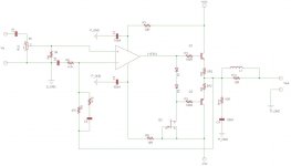
If it were me, I would make something like the amp I built way back in high school. R9/R5 sets the gain. C6 is the DC blocking cap, use something like 330uf non-polar cap here. C3 is frequency compensation and will be very small like 40 - 100pf, R10 creates a zero with C3. D1 & D2 must mount on the heatsink with Q1 & Q2 in order to sense temperature and adjust bias. Q3 can be any old J-fet, Vds>30V and Idss ~5mA. Use film caps for C1, C2, & C4. Use a 1/2W 10R resistor for R11 and wrap 22ga magnet wire around the resistor and solder it to each end to make L1. All the power GNDs should connect to a star GND point, and perhaps 1 or 2 Ohm resistor from signal GND to the star. Make sure to tie the speaker return current to the center of the two filter caps in the power supply. There is no way you will spend $150 on this, all the parts are probably in the parts bin in your lab class. Do you have to draw and create your own PCB?
Attachments
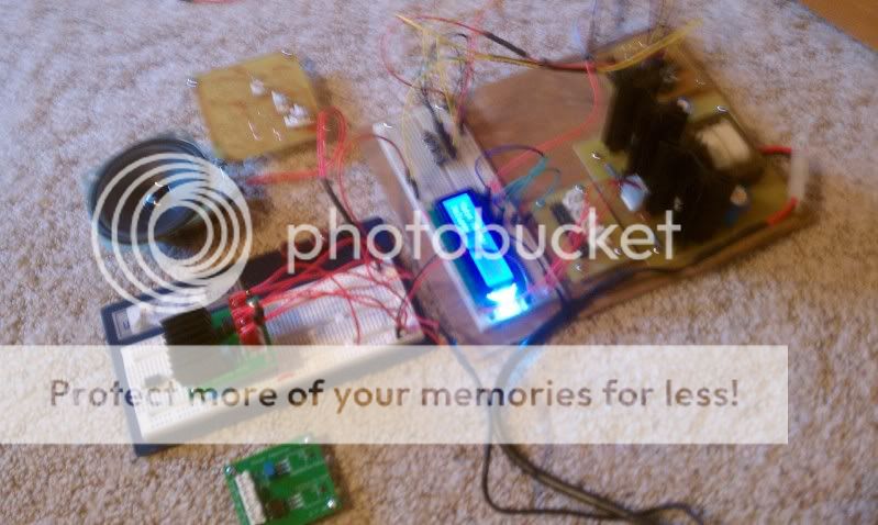
Got my opamps in today, and finished soldering it up. To be honest it works better then expected even with my very unideal design. It isn't high quality by any means (sounds about the same as those $15 computer speakers.
I still might remake it with some of the changes discussed in this thread, but for right now it is satisfactory:
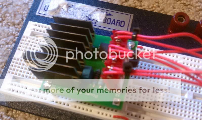
and the system thus far (well the parts that are working:
I really do appreciate all the help posed in this thread.
Also, the KISS acronym is still being taught 🙂 and yes we do have to make design the PCB's, but I'm at least familiar with that process.
edit: oh and sorry for the poor quality photos. It's Spring break right now so I'm away from the dorms and as such away from my camera (had to use phone).
I still might remake it with some of the changes discussed in this thread, but for right now it is satisfactory:
and the system thus far (well the parts that are working:
I really do appreciate all the help posed in this thread.
Also, the KISS acronym is still being taught 🙂 and yes we do have to make design the PCB's, but I'm at least familiar with that process.
edit: oh and sorry for the poor quality photos. It's Spring break right now so I'm away from the dorms and as such away from my camera (had to use phone).
I really do appreciate all the help posed in this thread.
Also, the KISS acronym is still being taught 🙂 and yes we do have to make design the PCB's, but I'm at least familiar with that process.
MJL21193 , myself and others have the PCB thing down pat. PM me and I can "hook you up" (CAD), chemistry , crude ways to get pro results. A $90 HP P1005 laser printer is the only "tool". 🙂
OS
So here's a question. If i don't have an input connected (so the input wire is an antenna), It plays conservative talk radio very clearly......
the transistors in the opamp's input stage are rectifying AM and producing audio. To stop this you need a high pass filter on the input - try 1K followed by 220pF to ground.
the transistors in the opamp's input stage are rectifying AM and producing audio. To stop this you need a high pass filter on the input - try 1K followed by 220pF to ground.
I'm more just curious how this works. Presumably the output stage acts as a crude low pass filter demodulating the AM signal, but why does it only pick up a single frequency on the AM band, I would expect more of a mixed signal static from radio interference since there isn't any components which would create a resonance in this design.
How long is the connection between the -input on the op-amp and the feedback resistors?
It is on a PCB, I checked the trace and it is about 1.5 - 2cm.
Also try some bypass caps on the supply lines say .001 uf to 100pf to ground as close to the opamp you can get.
A small cap across to the feedback resistor may work aswell,this will limit the bandwidth of the input signal being amplified.
What happens to the signal when you bridge your fingers across this resistor (try it with them slightly dampend aswell).
Most opamps have a bandwidth well above 1mhz and I have sucsessfully used a TL072 as a video inverting and non-inverting preamp.
The opamp and/or inputstage is amplifing the rf and gets rectified in the output stages.
This is very common.
Basicaly it is a untuned rf amplified radio right now.
If you use a bypass circuit on the input as suggested,what happens is that rf is shorted to ground due to the low resistance of the capacitor at those higher frequency's.
Do you have a copy of "the opamp handbook" or "opamp aplications"?
If not the links are somewhere in these threads.
The information in those manuals is priceless when working with opamps. jer
I'm more just curious how this works. Presumably the output stage acts as a crude low pass filter demodulating the AM signal, but why does it only pick up a single frequency on the AM band, I would expect more of a mixed signal static from radio interference since there isn't any components which would create a resonance in this design.
I've had the same problem with both hollow state and solid state designs. What's happening is that some stage is being overdriven by some strong RF signal, and is converting some stage into a detector. You typically hear just the strongest signal that can overdrive something. Weaker signals won't do that, and so aren't heard (though they can contribute to sonic degradation).
It's especially bad around my QTH since there's a 50KW AM xmtr not 30 miles to the north. That gets into everything.
I can't help but think back to when I first started out...
My first amplifiers wouldn't... amplify... but they made pretty good oscillators.
Oscillators didn't... oscillate...
Some amps picked up radio stations...
I always wanted to make a simple radio... and that never worked, even using the ZN414 (was it ?)
My first amplifiers wouldn't... amplify... but they made pretty good oscillators.
Oscillators didn't... oscillate...
Some amps picked up radio stations...
I always wanted to make a simple radio... and that never worked, even using the ZN414 (was it ?)
You might find this interesting if you haven't see it already:
http://www.passdiy.com/pdf/diyopamp.pdf
http://www.passdiy.com/pdf/diyopamp.pdf
Just to clerify the issue is really a non issue (as it is driven by other filters and devices and will never have a long wire connceted to the input). Was more interested in what was going on.
Miles Prower : Thanks that make sense. I went and looked up the broadcast location of the station I'm picking up and it turns out it too is 50kW station less then 4 miles from where I live (KFAB 1110) so the interference makes perfect sense.
Mooly: On the positive side I never have to think of new projects, you can just build off the undesired effects of your last project.
jkuetemann: Thanks, very interesting article. We briefly went over the stages of a ua741 opamp but this is much more detailed and a lot more useful. I've added it to my archive.
Much appreciated to everyone whose offered advice.
You might like to look at the LM3886. Not just a good amplifier, but lots of useful info in the applications section of the datasheet
www.national.com/pf/LM/LM3886.html
www.national.com/pf/LM/LM3886.html
The thing I was going to mention is that that there are a bunch of app notes that used to appear in the back of "op-amp" manuals (the ones with the various parts types in them) that had circuits to "boost" the power or current handling. They generally used a pair of external transistors... In essence that's what you've got there. It might be worthwhile just looking at how that was done... and then build something a little bit more refined if not for the dingbat professor then for your own learning.
There is one very neat one, where the output devices are not connected to the opamp's output pin at all...
_-_-bear
There is one very neat one, where the output devices are not connected to the opamp's output pin at all...
_-_-bear
- Status
- Not open for further replies.
- Home
- Amplifiers
- Solid State
- Class AB Amplifier - New to the analog world