Curious to know if there is any similarity between the below schematics:-
1. Original Marantz MA-9S2 Schematic:-

Detailed view of the above diagram is available in the service manual PDF of the MA-9S2 at here:
PDF manual for Marantz Amp MA-9S2
2. Chinese Clone board of MA-9S2:-

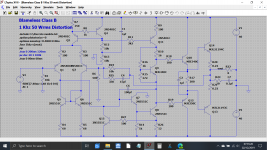
3. Locally Sourced Board by me for my new DIY amp:-

Photo of the board:

1. Original Marantz MA-9S2 Schematic:-
Detailed view of the above diagram is available in the service manual PDF of the MA-9S2 at here:
PDF manual for Marantz Amp MA-9S2
2. Chinese Clone board of MA-9S2:-
3. Locally Sourced Board by me for my new DIY amp:-
Photo of the board:
Last edited:
Similarities:
Four of the transistors in the "Bengal Tiger" have a heat sink drawn on the PCB legend, but no heat sink attached. I highly doubt you'll get 400 W out of it for any length of time.
Tom
- All three use emitter follower output
- The Chinese copy and the "Bengal Tiger" board both use Darlington outputs (so a stack of two emitter followers)
- The Marantz and Chinese copy both use the same (or very similar) front ends.
Four of the transistors in the "Bengal Tiger" have a heat sink drawn on the PCB legend, but no heat sink attached. I highly doubt you'll get 400 W out of it for any length of time.
Tom
Thanks for the reply guys.
Actually I bought a similar mono amp for my subwoofer long ago and was looking for same boards for new stereo build. That old boards had these transistors in line with main transistors and were attached to heatsink. That board is working perfectly fine but now that board isn't available so found these new ones and bought. Hope it works perfectly.
photo of the old board:

500w amp page1 | Vasp Electronics
I am more concerned about the sound quality than anything else. Was looking for something which acts as Class A at low volume levels and turns into Class AB at higher load.
Though I am also not looking for 400W output, 100-150W day long stable is enough for me. But still what if I add heatsinks to those transistor?Four of the transistors in the "Bengal Tiger" have a heat sink drawn on the PCB legend, but no heat sink attached. I highly doubt you'll get 400 W out of it for any length of time.
Actually I bought a similar mono amp for my subwoofer long ago and was looking for same boards for new stereo build. That old boards had these transistors in line with main transistors and were attached to heatsink. That board is working perfectly fine but now that board isn't available so found these new ones and bought. Hope it works perfectly.
photo of the old board:
But the seller mentioned class AB. Please check the specs and other details on the product page:Number #3 looks like a copy of Doug Self's 'Blameless Class B'.
500w amp page1 | Vasp Electronics
I am more concerned about the sound quality than anything else. Was looking for something which acts as Class A at low volume levels and turns into Class AB at higher load.
Last edited:
That was sample picture, Original board has small heatsinks, check the attached photo.Four of the transistors in the "Bengal Tiger" have a heat sink drawn on the PCB legend, but no heat sink attached. I highly doubt you'll get 400 W out of it for any length of time.
Tom


But the seller mentioned class AB. Please check the specs and other details on the product page:
500w amp page1 | Vasp Electronics
Use of terminology plays a big part here and my understanding of Class B as I was taught, and Doug's definition vary somewhat.
The 'Blameless Class B' is a actually an AB design like any other and it runs with quite a high bias of a little over 100 ma that produces the lowest possible distortion. Doug calls this 'Blameless Class B' and this is when the bias is set to the one single value that gives minimum distortion for the configuration used.
Compare this to many commercial amps that are deliberately under-biased to reduce heat production.
Increasing the bias above this critical optimum point moves the amp into Class AB (Dougs definition of AB), however the performance at levels above that transition suffers slightly compared to the optimum bias point.
I tested the amp for whole day and found that the main heatsinks remained super cool for all the playback time. I played low to moderate to loud volume levels and no heat. On the other hand my LM3886 heatsinks get warm after few minutes of playback and turn hotter after half an hour or so.
So should I play with the bias?
Though sound quality is fine but I feel the sound output level is bit low on +35 0 -35 supply, just little higher compared to my class D 3116 running on 19V supply. Is that okay? Or its an effect of replica 5200/1943 pairs? Or something to do with bias?
So should I play with the bias?
Though sound quality is fine but I feel the sound output level is bit low on +35 0 -35 supply, just little higher compared to my class D 3116 running on 19V supply. Is that okay? Or its an effect of replica 5200/1943 pairs? Or something to do with bias?
Last edited:
It is hard to make a determination of how loud one amp is vs another. You have to do measurements to see why you feel there is a difference such as setting each one to give the same level across your chosen load.
Transistors, replica or otherwise will not alter levels.
Your Class D amp on 19 volt rails will almost certainly run in a bridge configuration which is a bit like saying its a single ended design running on 38 volts.
Bias has no effect on perceived loudness.
Transistors, replica or otherwise will not alter levels.
Your Class D amp on 19 volt rails will almost certainly run in a bridge configuration which is a bit like saying its a single ended design running on 38 volts.
Bias has no effect on perceived loudness.
So what is affected by the transistors?Transistors, replica or otherwise will not alter levels.
I am curious to know what I will gain or lose by choosing some genuine alternative? Given that I don't have any complain with the sound quality during my initial testing.
Reliability is always a worry with fake parts.
As to what else is affected, well that depends to some extent on the circuit itself and how sensitive it is to such things as fT which is large signal current-bandwidth product, in other words how the device holds up at high frequency and at what frequency the current gain falls to unity.
Some older circuit designs are very susceptible to stability problems if parts of different spec are used, and conversely there are others that don't seem to mind what is used.
Wrong question.So what is affected by the transistors?
Transistors do not work alone but are part of a complex system, the power amp, with lots of other components, and subject to massive NFB.
So whatever you end hearing is the grand total of this complex system.
We don´t know which "genuine alternative" you will chooseI am curious to know what I will gain or lose by choosing some genuine alternative? Given that I don't have any complain with the sound quality during my initial testing.
")
But all is fine, if you are happy with the current one, then go on with it.
- Status
- This old topic is closed. If you want to reopen this topic, contact a moderator using the "Report Post" button.
- Home
- Amplifiers
- Chip Amps
- Class AB Amp Schematic Query - Is there Any Similarity Between These Circuits?