Once the transistors warm up to operating temp the bias appears to remain pretty steady. There is only a small thump at turn on but mostly due to the output cap charging.I agree the circuit looks pretty lame but you'd be suprised.
The curves for a 12AU7A / ECC82 show that already with 1mA flowing through the tube, at 0V Vgk (which would normally be the limit, quiescent Vgk is normally negative!), you already have 10V drop across the tube. This basically gives you the lower clipping limit - you are (in theory) left with 30Vpp of maximum swing, give or take a Vbe or two. This comes out as about 14W into 8 ohms max. For this sort of current, yes, the Vgk bias will be low (about 1V). If you drive the circuit with a low impedance source, you can drive the grid positive and get more swing, but at drastically increased distortion - approximating a +2V line for Vgk, gives you less than the 10V drop (say, 3V), but the anode voltage changes by about 7V for a positive swing of 2V grid to cathode, and nearly 30V for a negative swing of the same magnitude, so it is obvious that this is highly asymetric.
An ECC88 would give you about 3V more max swing at 1mA, increasing power output to 17W into 8 ohms.
The problem here is, 1mA is not enough to drive your BJT phase splitter with low distortion, you would need another follower stage to do it properly, or a different set of transistors.
In any case, the fact you are direct coupling the tube off the same power supply, robs you of some 10V of output swing, and requires of you to use the tube at currents so low that neither it or the following stage are very happy. In theory, with a 40V power supply, you should be getting about 22W into 8 ohms instead of 14 - perhaps not a very big difference in dB, until you consider that the 14W version has 20% less efficiency compared to the full swing 22W version, and in fact, makes 25% more heat than a properly optimized 14W amp with the same topology.
Note that I am not even going to mention BJT stage DC bias differences depending on the particular instance of the ECC82 used...
A design that would do a full 40Vpp swing with an ECC82 at say 15mA Ip, assuming CCS loaded plate of the tube, would need about 160V minimum for the B+. At 10mA, 130V is needed. Either would make the BJT stage more content, but would require AC coupling. An ECC88 would need about 85V at 15mA and about 72 at 10mA.
I have'nt started this circuit cold, using an external supply for the heater. I give the heater a few seconds before powering the circuit.
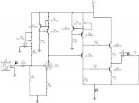
The tube + cathode resistor actually drop 1/2 B+ to set the output voltage. Vout for this circuit is = to the voltage at the base of the input trans - b e drops. With the grid sitting at 0 volts I think it is basically swinging between A1 and A2 operation, but none the less I get full output swing within a couple volts of the rails.
The tube + cathode resistor actually drop 1/2 B+ to set the output voltage. Vout for this circuit is = to the voltage at the base of the input trans - b e drops. With the grid sitting at 0 volts I think it is basically swinging between A1 and A2 operation, but none the less I get full output swing within a couple volts of the rails.
Intersting thing about this output is that when the base of the input transistor goes to B+ the output current goes to 0. So at turn on if the tube is cold and not flowing any current then the base goes toward B+ and the output current lowers.
jerluwoo said:The tube + cathode resistor actually drop 1/2 B+ to set the output voltage. Vout for this circuit is = to the voltage at the base of the input trans - b e drops. With the grid sitting at 0 volts I think it is basically swinging between A1 and A2 operation, but none the less I get full output swing within a couple volts of the rails.
It's certainly is moving into A2 or you would not get even close to full swing. You will get lower distortion for higher Ip this way, but also signifficant grid current. It will all look good as long as you drive it with a low impedance source. I think things will not look as good when you put a volume pot in front.
I am very interested in this thread. I have been using simple BJT buffers for a preamp, but now I want to add some gain and thought to do it possibly with a low-voltage tube stage. I have been looking around for designs. BTW, you may be interested to know, I found an article by Stefano Perugini who built a phono stage that runs off 2 x 12v batteries. He started out with traditional low voltage tubes (6GM8) but found he got more pleasing results with E88CC and E188CC. His final preference was E188CC.
I've been using my SB Audigy to drive these amps with no preamp with good results. The SB drives headphones pretty decent and doesnt seem to have any trouble driving the tubes.
And back to a previous question, almost no turn on thump with a cold tube, speaker moves back a little then centers again.
And back to a previous question, almost no turn on thump with a cold tube, speaker moves back a little then centers again.
Question to the moderators of the forum. Would it be ok to post download links to music samples recorded through this amplifier for others to hear? No complete songs just 59 sec. clips in high bitrate wave files.
After playing with the bias on the tube a bit, I settled on raising the grid just positive enough so the input signal kept from crossing 0 volts. This also made it posible to raise the current throught the tube to 3 ma. These changes made a noteable increase in sound quality. Most noticeable was a much punchier sounding bass.
Attachments
- Status
- Not open for further replies.
- Home
- Amplifiers
- Tubes / Valves
- Class A Tube BJT Hybrid