Hi Sdr Hastomo,
Amp anda cukup bagus - bunyinya jelas, murni......
I think it would be terrific, but can make one suggestion.
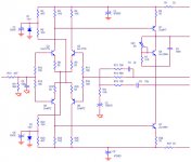
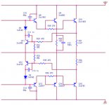
Each of the two drivers should have a 100R base stopper; and output devices should have a 10R base stopper. The 120R/100n should be connected between the two output device bases as shown, and you could delete the 270R resistors from driver base to emitter.
With these changes, it's a good design.........
Kapan anda membikinnya??
Cheers,
Hugh
www.aksaonline.com
Amp anda cukup bagus - bunyinya jelas, murni......
I think it would be terrific, but can make one suggestion.
Each of the two drivers should have a 100R base stopper; and output devices should have a 10R base stopper. The 120R/100n should be connected between the two output device bases as shown, and you could delete the 270R resistors from driver base to emitter.
With these changes, it's a good design.........
Kapan anda membikinnya??
Cheers,
Hugh
www.aksaonline.com
Oh,
I should add that R4 and R25 (both 1K5) are unnecessary. If the diff pairs use matched transistors, and if the input bias resistor matches the resistance from output to fb node, then balance in the diff pairs is automatic.
Cheers,
Hugh
I should add that R4 and R25 (both 1K5) are unnecessary. If the diff pairs use matched transistors, and if the input bias resistor matches the resistance from output to fb node, then balance in the diff pairs is automatic.
Cheers,
Hugh
Hugh,
I know it is common to omit these resistors in diff pairs, but is
it really true that it does not matter? From a theoretical point
of view I think it will make a difference. At the Q point, we will
have the same Icq through both transistors in the diff pair if
these are matched. However, if we omit the collecor resistor on
one of them we get different Vceq. This means the power
dissipation differs and, hence, the temperature, which will
make the transistors slightly unbalanced in practice. It will
probably not make much of a difference in this particular case,
but resistors are cheap. Probably 1k5 is not the optimal value
to achieve balance, though, since the other transistor has a
load in parallel with its collector resistor.
Or you can buy an old KSA50 on ebay....
😉
Here's a tip: put the trim pot base-emitter so that
when it gets old and dirty the bias goes to 0 instead
of infinity.

😉
Here's a tip: put the trim pot base-emitter so that
when it gets old and dirty the bias goes to 0 instead
of infinity.
dhengkoel,
are you sure the connections on the feedback network are drawn right? There is two lines leaving the first picture but only one is continued in the second picture. Also, I am not sure that all the connection points are correct.
What is the function of R14 by the way?
Regards,
Eric
are you sure the connections on the feedback network are drawn right? There is two lines leaving the first picture but only one is continued in the second picture. Also, I am not sure that all the connection points are correct.
What is the function of R14 by the way?
Regards,
Eric
R14 is the actual feedback resistor. The other two in
series with capacitors are the compensation, one looking
at the output and the other nested to the output of the
voltage gain devices. The diagram should show R12, 14, and 18
attached together on the left, which I can't see.
series with capacitors are the compensation, one looking
at the output and the other nested to the output of the
voltage gain devices. The diagram should show R12, 14, and 18
attached together on the left, which I can't see.
Hello Sirs,
I suggest that VR1 i sconnected between base and emiter.
If you connect it as shown in the schematic, the bias-voltage will increase to very high levels if the whiper of VR1 fails.
Otherwise, it look like a proper symmetric design 🙂 🙂
SE-amps are best avoided, or what do you think Mr. Nelsson?😉 😉
best regards😎
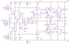
:: full schematic in one sheet ::

Is this schematic too close with your design KSA-50? I don't see the KSA-50 schematic yet. 🙁
I found the PCB in an old shop. Actually it's for 100w class AB amplifier. So I redesign it and decrease the voltage rail to 25v, but increase the Iq to 1.1A .....
Is that ok if I change the Q4 to PNP? [Because the PCB is ready ...]
Anyway thanks all for the comment; Here the full schematic in one sheet ....
Regards:
ragil.hastomo
Saya akan menyelesaikannya akhir bulan ini. [I will finished it at the end of this month.] 🙂Hugh: Each of the two drivers should have a 100R base stopper; and output devices should have a 10R base stopper.
I can't buy the KSA-50, that's too much expensive for me [sorry for that].Nelson Pass: Or you can buy an old KSA50 on ebay.... Here's a tip: put the trim pot base-emitter so that when it gets old and dirty the bias goes to 0 instead of infinity.
The diagram should show R12, 14, and 18 attached together on the left, which I can't see.
Is this schematic too close with your design KSA-50? I don't see the KSA-50 schematic yet. 🙁
I found the PCB in an old shop. Actually it's for 100w class AB amplifier. So I redesign it and decrease the voltage rail to 25v, but increase the Iq to 1.1A .....
Is that ok if I change the Q4 to PNP? [Because the PCB is ready ...]
Anyway thanks all for the comment; Here the full schematic in one sheet ....
Regards:
ragil.hastomo
Attachments
Morello said:
SE-amps are best avoided, or what do you think Mr. Nelsson?😉 😉
Like the plague.....
BTW, the KSA50 was a Krell design.
Nelson Pass said:
Like the plague.....
BTW, the KSA50 was a Krell design.
Dear Nelsson,
I don't understand what yourefer to as the plague?
Do you mean that the KSA50 is a plague?
😉
Best regards\Morello🙂
To "avoid [something] like the plague" is an English idiom that means one should stay away from the item in question.
However...
Seeing as how Nelson's Aleph amplifiers are single-ended, he's using the phrase in a humorous sense.
The KSA50 was a nicely executed class A circuit. You don't have to avoid it unless you want to.
Grey
However...
Seeing as how Nelson's Aleph amplifiers are single-ended, he's using the phrase in a humorous sense.
The KSA50 was a nicely executed class A circuit. You don't have to avoid it unless you want to.
Grey
Morello said:SE-amps are best avoided, or what do you think Mr. Nelsson?😉 😉
best regards😎
I think so ... but they need more power dissipation ...
I plan to make 'redesign' JLH SE amp after finished this project ... It's already on paper ... 🙂
Regards:
ragil.hastomo
Dear dhengkoel,
In fact, I can't see any valid technical reasons for designing a single ended power amplifier. I don't look at large amounts of even order distortiton as a benefit.😉 I like symmetric designs, in which even order distortions are cancelled.
Bets regards\Morello🙂
In fact, I can't see any valid technical reasons for designing a single ended power amplifier. I don't look at large amounts of even order distortiton as a benefit.😉 I like symmetric designs, in which even order distortions are cancelled.
Bets regards\Morello🙂
Morello said:Dear dhengkoel,
In fact, I can't see any valid technical reasons for designing a single ended power amplifier. I don't look at large amounts of even order distortiton as a benefit.😉
We must make both and hear the sound ... and choose wich sounding better ...
I like symmetric designs, in which even order distortions are cancelled.
Bets regards\Morello🙂
I think if we get npn pnp transistor with same caracteristic ...
Regards:
ragil.hastomo
dhengkoel said:
We must make both and hear the sound ... and choose wich sounding better ...
I think if we get npn pnp transistor with same caracteristic ...
Regards:
ragil.hastomo
The cancellation is ofcourse not perfect, but single ended amps tend to produce much more distortion than a push-pull design.
Best regards\Morello🙂
- Status
- Not open for further replies.
- Home
- Amplifiers
- Solid State
- :: class a symetric power amplifier ::