I thought I would share my first amp design and build project with the group here. I started out to build the JLH Class A, but it evolved into something a bit different. After completing the JLH I was not satisfied with the output offset drift. I also didn’t like the requirement for a regulated power supply, so I wound up switching to a differential input section with constant current sources for both the input and output sections. I stayed with the quasi-complementary output stage per the JLH design. My simulation showed very good results, although I struggled to get the transistor parameters right, so I have some question as to how good it really is. I have to say it sure sounds great to me, and my musician sons both said it sounded “Not Too Bad, ” so I call it the NTB🙂
I switched the output transistors from 2N3005 to 2SC5242 for better linearity and easier mounting. The bias current for the output devices is 1A. The power supply runs at +/- 15V. At 8ohms, that works out to about 14W per channel. A more conservative rating on the power supply of 13V gives more like 10W per channel. One critical component was the “current splitter” which feeds the two output devices. I had to find a device that had a very low base-collector output capacitance and went with the NTE373 at only 14pF. This greatly improved the overall performance from the original device I had chosen. The rest of the transistors are pretty common components. Because I had two transformers on hand, I went with separate power supply boards for each channel, each with 8800uF of filtering. There is another 2000uF on each amplifier board for local decoupling. I used separate ground returns for that.
I drew the schematics and laid out the boards using ExpressPCB. I have been very happy with their software and service. I did not get the solder mask or silkscreening option.
The heat sinks were found on ebay. After about 4 hours with no load, the maximum temperature I could measure on the output chips was about 150F. I have access to an IR thermometer from my work which sure makes things easier. My transformers are each rated at 2A, but they run pretty hot at about 140F. I wasn’t expecting a heat problem there, and I may add a heat sink to each of them.
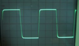
I have attached the schematics and an output waveform picture. I will post a few pictures of the build in a separate post. The squarewave output is at 20kHz, and +/-10V. The slew rate looks like about 20V/usec, although it is hard to tell from the picture. The amp is very quiet with no trace of hum at the speakers. It has an output offset of about 4mv.
I have learned a lot hanging around this forum so thanks to all of you. It sure has been fun working on this.😀
Joel
I switched the output transistors from 2N3005 to 2SC5242 for better linearity and easier mounting. The bias current for the output devices is 1A. The power supply runs at +/- 15V. At 8ohms, that works out to about 14W per channel. A more conservative rating on the power supply of 13V gives more like 10W per channel. One critical component was the “current splitter” which feeds the two output devices. I had to find a device that had a very low base-collector output capacitance and went with the NTE373 at only 14pF. This greatly improved the overall performance from the original device I had chosen. The rest of the transistors are pretty common components. Because I had two transformers on hand, I went with separate power supply boards for each channel, each with 8800uF of filtering. There is another 2000uF on each amplifier board for local decoupling. I used separate ground returns for that.
I drew the schematics and laid out the boards using ExpressPCB. I have been very happy with their software and service. I did not get the solder mask or silkscreening option.
The heat sinks were found on ebay. After about 4 hours with no load, the maximum temperature I could measure on the output chips was about 150F. I have access to an IR thermometer from my work which sure makes things easier. My transformers are each rated at 2A, but they run pretty hot at about 140F. I wasn’t expecting a heat problem there, and I may add a heat sink to each of them.
I have attached the schematics and an output waveform picture. I will post a few pictures of the build in a separate post. The squarewave output is at 20kHz, and +/-10V. The slew rate looks like about 20V/usec, although it is hard to tell from the picture. The amp is very quiet with no trace of hum at the speakers. It has an output offset of about 4mv.
I have learned a lot hanging around this forum so thanks to all of you. It sure has been fun working on this.😀
Joel
Attachments
Hi WuYit, thanks for your comments. During the development and testing I did try adding significantly more capacitance to the power supply. As expected, it lowered the power supply ripple, but I couldn't measure any difference in the output waveform, so decided to keep my board space a bit smaller. I think the constant current sources, substantial decoupling on the amp board, and careful grounding design contribute to the excellent PSRR.
Regards,
Joel
Regards,
Joel
It's very nicely built 🙂
You say this design "evolved" from the JLH.
Did you listen much to the original design as the single ended input stage plays a huge part in the distortion spectra produced by the amp and consequently also contributes to its very musical sound. It would be interesting to know if you noticed sonic differences between the two designs.
Mooly and CopperTop, thanks for the complements 🙂 I do not get any audible thump at power up. I have tried powering it up with the audio source both off and on. The music starts almost instantly. I have not looked at it with a scope though. Maybe I should...
Unfortunately, I did not spend much time listening critically to the single ended front end arrangement; now I kind of wish that I had 🙂
Joel
Unfortunately, I did not spend much time listening critically to the single ended front end arrangement; now I kind of wish that I had 🙂
Joel
Member
Joined 2009
Paid Member
I like it ! - from your description it sounds to me that you've done a very nice job of this.
I suspect folks would love to see a photo of the hardware and although there will be some 'armchair designer' suggestions for 'improvements' I think your design looks very good.
My 'armchair designer' suggestions would be to try a lower base-collector capacitor on the phase splitter to hear what impact it has on the sound, also to try adding resistors in parallel with the virtual ground capacitors (e.g. 1k5) and hear if it impacts the sound.
Last edited:
Joel,
Try removing the current mirror and increasing the degeneration on the differential................just a thought.
Jam
P.S. I also think the value of R6 might be way too high.
Try removing the current mirror and increasing the degeneration on the differential................just a thought.
Jam
P.S. I also think the value of R6 might be way too high.
Bigun, thanks for the kind words. I posted the pictures of the amp in the sticky pictures thread. Here's a link http://www.diyaudio.com/forums/solid-state/96192-post-your-solid-state-pics-here-172.html post 1719
I appreciate your ideas for improvement. My list already has a few things on it related to improving the PCB layouts🙂
Regards,
Joel
I appreciate your ideas for improvement. My list already has a few things on it related to improving the PCB layouts🙂
Regards,
Joel
C12 is really big...is this really needed?...say...so big one?
This uses to slow down the amplifier....and you see your square wave shows something less than perfect... well, very good job you have done..thank you as you are sharing with us.
regards,
Carlos
This uses to slow down the amplifier....and you see your square wave shows something less than perfect... well, very good job you have done..thank you as you are sharing with us.
regards,
Carlos
Bigun, I think your hunch is right regarding the cap on the phase splitter. I tried a capacitor in the 300pF range and I still had some ringing which I didn't like, but I bet there is an intermediate value that would be better. I may order a selection and do some further experimentation.
Joel
Joel
Jam, I calculated a value for R6 that was less (about half), but in simulation it showed minimum distortion at a higher level. I tried it with both and couldn't hear or see a difference so I went with the value from the simulation. Thanks, Joel
Member
Joined 2009
Paid Member
Bigun, I think your hunch is right regarding the cap on the phase splitter. I tried a capacitor in the 300pF range and I still had some ringing which I didn't like, but I bet there is an intermediate value that would be better. I may order a selection and do some further experimentation.
Joel
This issue with ringing can be a 'red herring'. I've looked at this recently and found some popular opinion that it's just a case of compensating the amp until it's smooth, as you've done, but I've seen some more considered thoughts on the internet pointing out the flaws in this approach which suggests that some ringing is 'OK' and preferable to over-damping.
For the kind of topology you have, with the LTP input, a compensation capacitor around 100pF should be much closer to the right value. In my own experiments I found the value had a subtle but repeatable impact on the sound. A value too high makes the sound a little dull, a value too low makes the high end too bright and somewhere in the middle you find the magic in the sound.
JLH was very wary of this kind of compensation too.
Keeping speaker cables reasonably short, and not using esoteric high capacitance speaker cables or speakers helps.
Last edited:
That is very interesting. Now I want to try taking it down to a lower value and see what happens; both on the scope, and with my ears. Guess I am going to have to order some more parts 🙂
Member
Joined 2009
Paid Member
It's all part of the fun for sure. A handful of values, and using some in parallel allows for quite a bit of experimentation. Modify one channel only and compare the two channels.
Be careful driving your amp with a square wave - I blew one up like that - square waves really stress the output devices. At full power it will blow it up before you have time to adjust your scope - at least it did for me !
Be careful driving your amp with a square wave - I blew one up like that - square waves really stress the output devices. At full power it will blow it up before you have time to adjust your scope - at least it did for me !
Last edited:
We deeply regretted that square wave event caused by an allegedly advanced, but in point of fact deficient compensation method.
😀
😀
Member
Joined 2009
Paid Member
my musician sons both said it sounded “Not Too Bad, ”
Joel, very impressive (first amp or not) I doubt any additional congrats compare with NTB. I really like the clean build, and clean square wave response (20V/us seems sufficiently fast to me for 10V rails). Your thought out responses reveal the care that went into this.
Interested in hearing what your final tweaked preferred listening values are.
Thanks
-Antonio
This uses to slow down the amplifier....and you see your square wave shows something less than perfect... well, very good job you have done..thank you as you are sharing with us.
regards,
Carlos
It is a 20 kHz square wave, and it is an audio amp, not a MW transmitter. For the second you need a better square wave indeed.
- Status
- Not open for further replies.
- Home
- Amplifiers
- Solid State
- Class A Sounds Mighty Sweet!