Can I ask some question ?
Can I simply parallel two ZAC amps (input -input and output-output) to get benefit from lower overall distortion and improve damping like in Zen amp ? Thanks anyway.I like the design and plan to built it.
Can I simply parallel two ZAC amps (input -input and output-output) to get benefit from lower overall distortion and improve damping like in Zen amp ? Thanks anyway.I like the design and plan to built it.
Re: Can I ask some question ?
I'm sure you can parrallel the Fets. But I would put 0.5ohm (5W non-inductive) resistors between the source and ground. This (I think) ensures the Fets work together. Try it the resistors and then with out.
By the way I have visited Chang Mai. Great town lovely people.
sceadu said:Can I simply parallel two ZAC amps (input -input and output-output) to get benefit from lower overall distortion and improve damping like in Zen amp ? Thanks anyway.I like the design and plan to built it.
I'm sure you can parrallel the Fets. But I would put 0.5ohm (5W non-inductive) resistors between the source and ground. This (I think) ensures the Fets work together. Try it the resistors and then with out.
By the way I have visited Chang Mai. Great town lovely people.
This amp is sweet. 😀
I am making a little amp contest to see what will power my future Front and Back loaded horns.
I made a quick and dirty ZCA. My test heatsink is awful, I know.
I don't use a choke but a PowerReg, a gyrator type regulator. No humm at all. PS Ripple is 2mV, I think. Maybe I have to increase the cap from the gyrator...
Some picks:
http://picasaweb.google.com/maxlorenz24/SINGLEENDEDCLASSAMOSFETAMP
At its side is a Destroyer X DX HR II module 😎
Thanks again mhouston. It is so much fun...especially the part when we power-on and don't know what will happen...OK, I use a variac but I get excited anyway 😀
Cheers,
M
ZCA - yet another
Feel free to call me Mark.
A lot of builders have made ZCAs and all enjoyed them. You must tell me what you think of the sound. You do need efficient speakers. Anything 90db and over is good. Also don't be scared to have it drive big 12" woofers. As long as you have the efficiency it should not be a problem. My ZCA drives a 3-way 12" woofer based 63litre boxes and it sounds very complete.
It looks like you made the heatsinks. A bit of TIG/MIG welding? I front-end my ZCA with a small valve preamp. This is a knockout combination.
Good work. Tell me about the sound.
Also we all shield our eyes when we first power-up. Yes it is exciting and rewarding when it just "WORKS". I just finished another SS preamp (lookout on the gallery) I had been working on for weeks. And at the smoke test heaven and hell play a tug of war. Just have faith and do all your final checks. And bless yourself helps too.
Hi,
the 15r load resistor tells you that a 15ohm speaker gets best power from this circuit.
The stage is a single ended ClassA topology.
The quiescent current (bias) is 12V/15r=800mA.
The peak currents into the load are +800mA and ~-800mA when the load is 15r.
The maximum power is 0.8^2*15/2=4.8W
Two channels will consume ~40W and total maximum power ~9.5W.
But into 8ohm speakers you get only 2.56W/ channel.
If you use an 8ohm speaker, then I suggest that the load resistor be lowered to 10 to 12ohms and see how hot the FET gets when you re-bias the circuit. If the temperature is tolerable try lowering to 8r0 and check again.
At Rload=8r0 the bias current is 1.5A and the FET dissipation is upto 18W (mighty hot). Maximum power is now ~9W/channel. PSU load is now 36W/channel.
All the caps can be 35V or higher.
All the resistors can be 250mW or higher.
Parallel FETs should be matched (Vgs better than 10mV @ operational current) and require source resistors.
When the math don't work
If the ZCA was linked to your calculator and all the laws of electric ccts. worked as they should, you could drop the load resistor (RL) to 8 ohms. And if you know anything about the AC only version of the ZCA the + volts end of the 8 ohms can theoretically be folded to ground. So when the speaker looks back at the cct. the only impedance it sees is the 8 ohms because the output cap blocks all DC and only allows AC through. And there is an active device generating voltages across this 8 ohm engine. The varying voltages are the audio signal.
So the simplistic and AC version of this amplifier, ACORDING TO THE SPEAKER IS AN 8 OHMS RESITOR WITH A VARYING VOLATGE ACROSS IT.
In a FET there is a lot of physics to overcome. To help with this we apply bias voltages, we require cooling and an infinite amount of power across the FET. Not infinite voltage just a very black PS. SE devices have no PSRR. This is where it all starts to fall apart. For the cct. I have described in my ZCA article, for the FET used, the cooling I could provide and the voltages stated the lowest load I could stabilize that cct. IS 15R. Note I said stabilize the cct. With all the problems with FETs used in audio at least they have a negative temp. coefficient. So they are a little harder to burnout. This here is a good point but it also works against FETs.
It took me months to get the load as low as I did with the other parameters as they are. Yes theoretically the load should be 8ohms. But in reality I found 15R to be the lowest load I could safely use. If you lower the PS voltage then you will probably be able to lower the load R. But then you start to lower dynamic headroom. One of the reasons valve amps make excellent audio amplifiers (I think the very best) is the huge dynamic headroom (I’m expecting arguments about this point). So to get the load lower drop the PS voltage. A compromise must be made. I think MUSICALLY I found that point for the the cct. I described. If you build the ZCA as in the cct. and its associated PS you will probably agree.
AndrewT said:Hi,
the 15r load resistor tells you that a 15ohm speaker gets best power from this circuit.
The stage is a single ended ClassA topology.
The quiescent current (bias) is 12V/15r=800mA.
The peak currents into the load are +800mA and ~-800mA when the load is 15r.
The maximum power is 0.8^2*15/2=4.8W
Two channels will consume ~40W and total maximum power ~9.5W.
But into 8ohm speakers you get only 2.56W/ channel.
If you use an 8ohm speaker, then I suggest that the load resistor be lowered to 10 to 12ohms and see how hot the FET gets when you re-bias the circuit. If the temperature is tolerable try lowering to 8r0 and check again.
At Rload=8r0 the bias current is 1.5A and the FET dissipation is upto 18W (mighty hot). Maximum power is now ~9W/channel. PSU load is now 36W/channel.
All the caps can be 35V or higher.
All the resistors can be 250mW or higher.
Parallel FETs should be matched (Vgs better than 10mV @ operational current) and require source resistors.
If the ZCA was linked to your calculator and all the laws of electric ccts. worked as they should, you could drop the load resistor (RL) to 8 ohms. And if you know anything about the AC only version of the ZCA the + volts end of the 8 ohms can theoretically be folded to ground. So when the speaker looks back at the cct. the only impedance it sees is the 8 ohms because the output cap blocks all DC and only allows AC through. And there is an active device generating voltages across this 8 ohm engine. The varying voltages are the audio signal.
So the simplistic and AC version of this amplifier, ACORDING TO THE SPEAKER IS AN 8 OHMS RESITOR WITH A VARYING VOLATGE ACROSS IT.
In a FET there is a lot of physics to overcome. To help with this we apply bias voltages, we require cooling and an infinite amount of power across the FET. Not infinite voltage just a very black PS. SE devices have no PSRR. This is where it all starts to fall apart. For the cct. I have described in my ZCA article, for the FET used, the cooling I could provide and the voltages stated the lowest load I could stabilize that cct. IS 15R. Note I said stabilize the cct. With all the problems with FETs used in audio at least they have a negative temp. coefficient. So they are a little harder to burnout. This here is a good point but it also works against FETs.
It took me months to get the load as low as I did with the other parameters as they are. Yes theoretically the load should be 8ohms. But in reality I found 15R to be the lowest load I could safely use. If you lower the PS voltage then you will probably be able to lower the load R. But then you start to lower dynamic headroom. One of the reasons valve amps make excellent audio amplifiers (I think the very best) is the huge dynamic headroom (I’m expecting arguments about this point). So to get the load lower drop the PS voltage. A compromise must be made. I think MUSICALLY I found that point for the the cct. I described. If you build the ZCA as in the cct. and its associated PS you will probably agree.
Re: When the math don't work
But I don't think the enquirer appreciated that.
I agree, as posted the amp suits the higher impedance of 15ohms, not 8ohms.mhouston said:....I could provide and the voltages stated the lowest load I could stabilize that cct. IS 15R. Note I said stabilize the cct. With all the problems with FETs used in audio at least they have a negative temp. coefficient. .......
It took me months to get the load as low as I did with the other parameters as they are. .......But in reality I found 15R to be the lowest load I could safely use.
But I don't think the enquirer appreciated that.
AndrewT
Andrew do you have some links to audio gear you have made. I'm always intersted in what others are building. It gives me ideas.
Andrew do you have some links to audio gear you have made. I'm always intersted in what others are building. It gives me ideas.
gmilitano said:Hi John,
Nice work with the Capacitance Multiplier. Can you post a picture of your new power supply? Do the transistors in the Capacitance Multiplier need a heat sink?
Bean meaning to post a pic of the cap multiplier PS for a long time...
I added another 10k uF input cap. The output cap was also changed--from 1000uF to 4700uF. Can't say that I could hear any improvement in the sound, but I still think it sounds great, so I kept the changes.
It turns out the TIP3055 does get as hot (or hotter) than the MOSFETs, and the load resistors, so I might redo it so I can mount it to the case for better heat dissipation.
Really, I haven't been able to do any direct comparisons between the original PS and the cap multiplier. The cap multiplier is quiet, and has no thump when its turned on. But as to which one I think actually plays the music better? Don't know.
I do still prefer the passive linestage though.
Attachments
Hi Mark. Sorry for the late reply.
I use an Audio Nirvana super10 fullrange driver on a 2:3 downsized replica of the Tannoy Autograph front and back horn loaded, corner type enclosure. Sensitivity must be higher than 97db/W/m. 😎
http://picasaweb.google.com/maxlorenz24/DIY/photo#5165544981065273714
I am getting decent peaks and midbass is becoming punchier.
I did not commented further about sound because the description at your site is quite accurate. I should add that voices are extremely seductive and one can hear subtleties and inflections previously unnoticed...another strange thing I noticed is that, while making a relaxed listening experience, one can pick-up better the mistakes of the players! 😱
Hi Kinnja,
The guys at pinkfishmedia have played a lot with gyrators. The PowerReg I am using is built around one:
http://www.pinkfishmedia.net/forum/showthread.php?t=39306
You may want to take a look.
The experts say that the type of cap and transistor influence sound.
Cheers,
M
Sounds of ZCA
maxlorenz
Everyone who has described the sound of the ZCA describes it like you. They all say there is great clarity and definition in the sound. A number of my audio club member friends have also been amazed by the transparency of the ZCA. It plays exctremely well for shuch a simple design.
Also you appear to have high efficiency speakers so it should play loud. The build looks good and clean.
Dear Mark,
You are extremely kind. I never make anything clean 😀
The truth is that it is a sin not to build your nice little amp! IMHO.
Best regards,
M
Also you appear to have high efficiency speakers so it should play loud. The build looks good and clean.
You are extremely kind. I never make anything clean 😀
The truth is that it is a sin not to build your nice little amp! IMHO.
Best regards,
M
ZCA II
I have been thinking of the same amp with 2N3055s in darlington pair config.
But yet to happen.
I have been thinking of the same amp with 2N3055s in darlington pair config.
But yet to happen.
maxlorenz,
Another ZCA! Good stuff. I need to try one of these too! I was thinking LM350 for the current source.
Kinnja,
Thanks for the update.
Cheers
Another ZCA! Good stuff. I need to try one of these too! I was thinking LM350 for the current source.
Kinnja,
Thanks for the update.
Cheers
Hi guys, Mark,
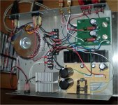
I finally put one monoblock into a decent DIY box. My power supply uses the "charge-transfer" concept from -ECdesigns- (alike "never-connected" PS from JC, I think) plus the previously mentioned PowerReg gyrator based regulator.
Photos:
http://picasaweb.google.com/lh/photo/8DI-hfrJQ2OkYHDig9m4XA?feat=directlink
http://picasaweb.google.com/lh/photo/DBPGMEHS_kM2f_Pev5oCZg?feat=directlink
Here is the charge transfer concept, post # 2347:
http://www.diyaudio.com/forums/showthread.php?threadid=79452&perpage=25&highlight=&pagenumber=94
Listening to mono recordings, voices are sooo sweet and articulated...
Any advice is welcome.
Cheers,
M
Not sure about the power supply techniques you are talking about. I have not heard of them before.
Your build of the ZCA is very different to all the others I have seen. Still if it works and sounds good, why not. It looks like you made your own enclosure.
How does it sound?
Your build of the ZCA is very different to all the others I have seen. Still if it works and sounds good, why not. It looks like you made your own enclosure.
How does it sound?
Hi Mark,
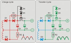
I attached (I think ) a concept diagram of a simplified charge transfer PS. It is supposed to disconnect mains noise from active circuit by using a Mosfet as interruptor between two main PS caps while rectifier diodes are passing current, on the rest of the cycle the Mosfet connects both caps. I know my explanation is bad but you will see by yourself with the diagram...I hope.
Yes, the box is completely DIY and the parts are very cool. The hotter parts are in fact the power resistors that form part of the charge transfer supply and the little transformer itself: 120VA for a monoblock.
Maybe I could someday reduce load R to 10 or 8 Ohm 😀 to get more power, as was discussed before.
It sounds very charming and clean. I like the articulation of the instruments and the nuances that can be perceived on the voices, but I've not compared AB with the previous PS. I could short the charge transfer I/O perhaps and see...
Regards,
M
I attached (I think
) a concept diagram of a simplified charge transfer PS. It is supposed to disconnect mains noise from active circuit by using a Mosfet as interruptor between two main PS caps while rectifier diodes are passing current, on the rest of the cycle the Mosfet connects both caps. I know my explanation is bad but you will see by yourself with the diagram...I hope.Yes, the box is completely DIY and the parts are very cool. The hotter parts are in fact the power resistors that form part of the charge transfer supply and the little transformer itself: 120VA for a monoblock.
Maybe I could someday reduce load R to 10 or 8 Ohm 😀 to get more power, as was discussed before.
It sounds very charming and clean. I like the articulation of the instruments and the nuances that can be perceived on the voices, but I've not compared AB with the previous PS. I could short the charge transfer I/O perhaps and see...
Regards,
M
Attachments
Maxlorenz
Thanks for the cct. and explanation. I understand how it works. And I had not seen it before.
Your listening notes for the ZCA are similar to most who build the amp. Transparency and detail seem to rate high on the evaluation.
If you wanted to try a touch of negative feed back try a small resistor in the emitter leg. This will be local feed back.The resistor to try should be between 1 and 2 ohms if the load is 15omhs. I haven't done it but thought about puting one in with a shorting switch to turn it on and off.
Also if you have stuck closely to my values for the components and close to the Voltage do not drop the load (15ohms) lower. The reason is that the FET is on the point of instability now. Putting more load on it (lower load resistor) may allow it to drop into instability. I have tried it and for 24V PS 15omhs is as safely low as you can go. But please yourself.
If you like the ZCA you will really like my single transistor preamp. One 2N3055 per channel. Sounds crazy but large power transistors have some excellent low signal qualities and that's what I picked up on. e-mail me and I will give you an article I wrote about it including images and schematic. mwhouston@iinet.net.au
- Status
- Not open for further replies.
- Home
- Amplifiers
- Solid State
- Class A Mosfet Amplifier and PS