The 20% I mentioned is just a number, to make it easy.
The XA200.5 does a max of 58V, which is a little higher than 200W/8.
An important item you seem to have failed to understand is that the XA amps are not regular PP Class A.
Would you be so kind to take a couple of minutes and explain how it works?
Thanks sir!
thanks Pablo for your reply. No I wasn't saying that. I have a soft start circuit.
Thanks for your intervention anyway.
I probably need to put some picture to support my question.
Well, that might help Stefano 🙂
listen to Pablo
what he told you is right on the money: a short duration peak current will have no bearing on long term averaged value like RMS current, thus your question has no basis.
what he told you is right on the money: a short duration peak current will have no bearing on long term averaged value like RMS current, thus your question has no basis.
what he told you is right on the money: a short duration peak current will have no bearing on long term averaged value like RMS current, thus your question has no basis.
you are brutally direct with your statements...but actually spoke the truth 🙂
Since you bring it up, yes I am talking about power consumption. The inrush current is something else that needs to be dealt separately and actually depends on your capacitance load combined with your actual power load and also the parameters of your transformer (mostly).
A simple either thermistor or better control circuit with soft start can easily deal with this.
If the latter is chosen, if the amp is particularly hefty, then you need to tune your resistor start up along with timing and power dissipation.
Once all your parameters are dealt in even the bigger class A amp can be started up in a flick of a switch.
I diverged it a little bit, but yes inrush current doesn't account in any way on the power consumption of the amplifier.
However tomorrow I will post some pictures taken with my measurement equipment, might help explaining a bit better what my question is all about.
😎
Stefano. all Power cunsumption on class A is given at IDLE. there is no peaks at idle. there is no signal at idle. there is no current peaks. there is no charging it is just a steady voltage and a steady current called bias. nothing more, nothing less. (well. almost)
Power cunsumption is railvoltage*bias*2.
Power cunsumption is railvoltage*bias*2.
how it works ?
Over the last 2 decades, Papa has focused on Single-Ended power output, at a lower total dissipation level.
Theoretical maximum efficiency of PP class A is 50%.
Max efficiency of SE class A is 25% : a 200W class A Single-Ended output stage has a minimum dissipation level of 800W.
The XA.5 series is a mix of SE and PP, which means that the theoretical maximum efficiency figure lies between 25% and 50%.
Add to that :
- the supplement on the rails (voltage ripple, drive loss, a little extra to enable 800W peak in 4 ohm, plus some slack)
- double the rail losses, due to fully symmetrical operation
- dissipation of the front end
- transformer loss (some 5% for a good toroidal transformer)
- bridge rectifier dissipation
- dissipation in the electrolytic cans
Power consumption is output stage dissipation plus all other sources of energy loss
Last edited:
Look closely at the output stage sections (XA160.5) :
http://www.ultima.su/images/lib/brand/pass_labs5.jpg
100mF or 200mF in the can department does make a difference in power consumption, but at a figure of 700W it's less than 1%
(higher capacitance means shorter charge periods, means higher current level, higher forward voltage, higher dissipation)
http://www.ultima.su/images/lib/brand/pass_labs5.jpg
100mF or 200mF in the can department does make a difference in power consumption, but at a figure of 700W it's less than 1%
(higher capacitance means shorter charge periods, means higher current level, higher forward voltage, higher dissipation)
The argument is that if for a given amount of bias you have more capacitance, your peak current to charge this capacitance will be much higher than if you had less capacitance, which will reflect in an higher RMS current at the primary
The current will indeed be higher but also of smaller duration. The power content of the puls will remain the same because the power extracted by the load will be the same (apart from some few % deviation because of secondary effects like heating of wire etc).
Also, the power on the primary side is the power taken from the secondary side plus some transformer losses. In principle, if it wasn't for the losses, power into primary = power from secondry but there may be say 10% losses.
Although it would vary somewhat with power supply caps, not significantly.
Jan.
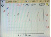
As promised some pictures with measurement results.
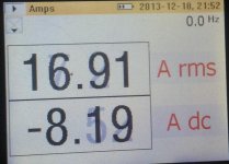
First is the current waveform from the rectifiers to the bank of electrolytic (please ignore the frequency reading which is of course 120Hz I used my Fluke power meter instead of my current probe with the scope, but it still serves the purpose). whle the second pictures shows the actual numerical reading, where it can see how the RMS value is significant higher with a DC component (I don't know why the DC is not shown on the waveform..I will retake this measurements with the current probe most likely, but I am sure we all know this is peanut butter and jelly anyway!
While the measurement (not shown here because not useful) from the electrolytic bank to the output board shows a proper roughly 4A bias I have on the amp with minor ripple.
This brings the behavior of the current on the primary to be like the one shown in third picture.
With this current the power consumption exceeds 1.2KW although I have 8A bias per side at +/- 42V.
Obviously the AC component is due to the electrolytic filter. And this correlates to my original question: how come the power consumption is so much higher than what expected?
Jan, thanks for your explanation, it makes total sense.
Attachments

Last edited:
What part of the XA.5 is SE?
the output stage has a mixture of PP and SE arrangement. You might want to consider doing some reading around about these things before enjoying the carousel. You seemed to have followed this forum long enough to be able to understand at least a little bit of what is going on!!! 😱

😎
In that case, you know that's it's done differently in the Xs (active, instead of resistors), and why you should not compare numbers of the XA with those of the Xs.
(beauty of a Fluke meter is that everytime you look at one, it tells you in printing that it can be a Fluke)
(beauty of a Fluke meter is that everytime you look at one, it tells you in printing that it can be a Fluke)
In that case, you know that's it's done differently in the Xs (active, instead of resistors), and why you should not compare numbers of the XA with those of the Xs.
(beauty of a Fluke meter is that everytime you look at one, it tells you in printing that it can be a Fluke)
yes I know that. XS has active SE while XA passive. Mine is active indeed.
Yes you can tell by the font 🙂
Anyway, if anybody has an explanation to this I will very gladly listen to it.
It seems not to be a trivial question...or is it?
😎
Look closely at the output stage sections (XA160.5) :
http://www.ultima.su/images/lib/brand/pass_labs5.jpg
100mF or 200mF in the can department does make a difference in power consumption, but at a figure of 700W it's less than 1%
(higher capacitance means shorter charge periods, means higher current level, higher forward voltage, higher dissipation)
oops. Forgot about the SE bias at low power levels. Guess that does make it quasi SE/PP.
@stefanoo,
Just forgot we had been around this circle before. I figured you would have bought an XA.5 by now and improved it.
Last edited:
May be I have a declaration for Stefano's irritation which I understand in this way, that primary power consumption seems to be much above that from secondaries (losses neglected):
From his pictures we see that duration dT and distances of primary and secondary current impulses are identical. Therefore it is logical that primary impulses result from secondary impulses. Now let's assume that area A under a single current impuls is 2/3 of that rectangular area which its current A would form with pulse duration dT:
A = 0,67*A*dT
Looking on primary impulses we can estimate that 60Hz is representative for 4*dT.
Peak current is 23A (approx.). If this were a continuous current, power consumption from primary would be 23*115V = 2645W.
But we have no continous current, we "only" have peaks. Area under both peaks is only 33% compared to area for continuous current, which gives us 873W power consumption - a good figure for approx. 8A bias current.
That means that amp only draws current out from mains while rectifier loads elcap bank.
If Stefano had used a RMS-current meter, he probably had not become irritated....
explanation
In (decent) engineering schools, it's taught on several occasions always to question the meter and one's own sanity.
(not likely to be included in a psychology curriculum)
May be I have a declaration for Stefano's irritation which I understand in this way, that primary power consumption seems to be much above that from secondaries (losses neglected):
From his pictures we see that duration dT and distances of primary and secondary current impulses are identical. Therefore it is logical that primary impulses result from secondary impulses. Now let's assume that area A under a single current impuls is 2/3 of that rectangular area which its current A would form with pulse duration dT:
A = 0,67*A*dT
Looking on primary impulses we can estimate that 60Hz is representative for 4*dT.
Peak current is 23A (approx.). If this were a continuous current, power consumption from primary would be 23*115V = 2645W.
But we have no continous current, we "only" have peaks. Area under both peaks is only 33% compared to area for continuous current, which gives us 873W power consumption - a good figure for approx. 8A bias current.
That means that amp only draws current out from mains while rectifier loads elcap bank.
If Stefano had used a RMS-current meter, he probably had not become irritated....
Thank you sit this is the best exposition I got so far.
I will redo measurements using current probe instead.
I do still think that the AC measurement is got to be precise on this instruments.
Basically with this conclusion you are assessing that the reading from the meter is wrong!
The only problem with my ancient scope is that it won't give me rms reading...that is why I need soon to get a decent Agilent scope of something similar.
I will retake measurements tonight and do some manual calculation.
If that was the case where no DC component would be present only peak charge for elcaps, I would be frankly and pleasantly surprised!
I don't know if I mentioned that but I have 450mF of total cap similar to XS series.
In (decent) engineering schools, it's taught on several occasions always to question the meter and one's own sanity.
(not likely to be included in a psychology curriculum)
Yes mostly back on the days I guess! Then I guess you don't have to trust anything!
Yes I understand what you are saying and in this case it seems one of these cases where an expensive instrument might be wrong for some unknown reason!! I will doubl check that again!
oops. Forgot about the SE bias at low power levels. Guess that does make it quasi SE/PP.
@stefanoo,
Just forgot we had been around this circle before. I figured you would have bought an XA.5 by now and improved it.
Ahaha
Basically with this conclusion you are assessing that the reading from the meter is wrong!
You were only misleaded from primary current peaks.
- Status
- Not open for further replies.
- Home
- Amplifiers
- Pass Labs
- Class A Bias