
I'm sorry but if you think I'm anyone special or important, you'd be wrong. I'm an average working tech. Virtually any tech who does this work, for a living knows what I know. The only difference is that I've been doing tech support a while longer so people recognize the name.
Start with 1k 9/10 to pin 7 and 100 ohm gate resistors if you're going back to the Z34s. If the FETs run hot. post waveforms from 9/10 and from the actual gate leg of the FETs.
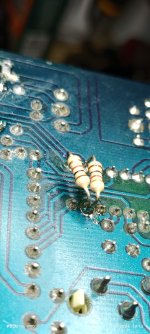
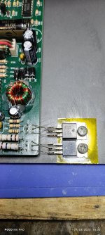
The resistors are OK like that. Make sure that they clear the bottom cover when you reassemble the crossover.
A scope will tell you precisely what you have. You sometimes have to do a few things to make sure it's not misleading you but, for most things in repair, especially those concerning drive waveforms, the scope wins.... if you take the time to learn to use it. Few people do... and every time I see someone posting drive waveforms with AC coupling... I can't say because I'll likely get banned.
Start with 1k 9/10 to pin 7 and 100 ohm gate resistors if you're going back to the Z34s. If the FETs run hot. post waveforms from 9/10 and from the actual gate leg of the FETs.
The resistors are OK like that. Make sure that they clear the bottom cover when you reassemble the crossover.
A scope will tell you precisely what you have. You sometimes have to do a few things to make sure it's not misleading you but, for most things in repair, especially those concerning drive waveforms, the scope wins.... if you take the time to learn to use it. Few people do... and every time I see someone posting drive waveforms with AC coupling... I can't say because I'll likely get banned.

Basic car audio electronics is your website right? If so you're special! I found that site years ago and it help me a lot.
So I'm going go back to the previous circuit that I had with the Z34Ns, and posts waveforms of pins 9/10 and both of the FETs gates. I will post in a few hours, going to get some sleep.
I'm also going to check if the D44VH10 is available locally. I'm guessing why the waveforms looks so weird is because the TIP 41 and Z34Ns can't operate at 114Khz efficiently?
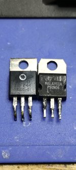
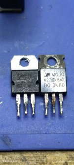
The TIP41s are not well suited for (relatively) high frequency square wave operation. The D44s are and were used in the old Rockford P45s for many years.
The Z34s are perfectly suited for this supply but you have to drive them properly. The Z34s are better than most any BJT. Unless you just want to see if you can make them work, I wouldn't bother with them. FETs are going to outperform them.
The Z34s are perfectly suited for this supply but you have to drive them properly. The Z34s are better than most any BJT. Unless you just want to see if you can make them work, I wouldn't bother with them. FETs are going to outperform them.
So just stick with the Z34Ns, and post the waveforms? 100 ohms resistors on the gates and 1K Ohms on the pulldown circuit.
What about the 1 ohm resistors on the emitter/source?
What about the 1 ohm resistors on the emitter/source?
I don't think they're doing much but they may serve to make the FETs run a bit cooler. Try it both ways if you want to know if they make a difference.
I did try it both ways before, without them the gate drive voltage was higher. But I can't remember if the pulldown resistors were in circuit or not.
Drive voltage amplitude on the scope or a higher reading with a multimeter?
10v of amplitude is the sweetspot for standard threshold Enhancement mode FETs like those used in high-current applications in car amplifiers. You can continue to compare the meter readings to what you see on the scope but for regulated power supplies, you can't tell much with a multimeter. For unregulated supplies, they can be somewhat more useful but they can't tell how fast the drive circuit is pulling the voltage down to ground.
Something I failed to mention is that, when dealing with regulated supplies like this, the long deadtime that you have when after the duty cycle is reduced can fool you into thinking that everything is OK, even if it's not. To force the duty cycle to increase, reduce the 12v supply voltage to the crossover. The 594 will have to increase the duty cycle to maintain the target rail voltage with the lower supply voltage. Decrease the voltage until the duty cycle no longer increases or until it shuts down from low voltage. How much more do the FETs heat up when the duty cycle is near 50%?
Sorry about the late reply, i could have sworn i wrote a reply saying that i was going to get some sleep before swapping in the Z34Ns. So you want to know how close to 50% the duty cycle is?

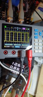
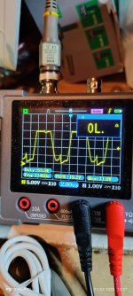
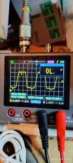
It appears that the scope wasn't triggering properly. An adjustment of the trigger level would likely get you what you expect.
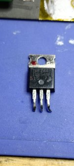
If you have two Z44s, use those.
If you have two Z44s, use those.
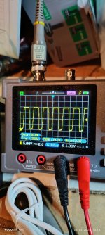
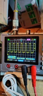
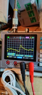
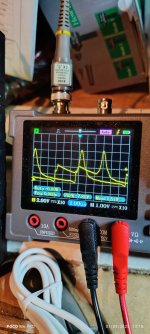
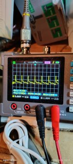
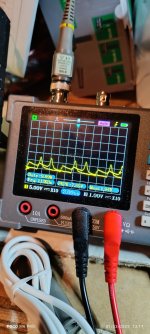
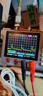
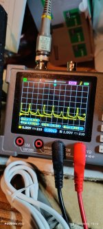
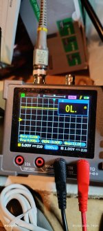
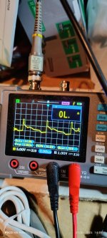
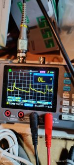
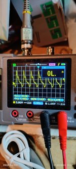
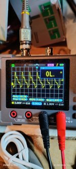
That's what I've told. So I used the other of MOSFETS, and even at 12.6 volts the FETs get hot and the source resistors get extremely hot. You'll see the duty cycle in the images. Lowering the voltage to 9 volts it wouldn't turn on until I increased the current. The source resistors started smoking slightly.
The waveforms shown are from the pins 9/10, gate pins and also the drain pins.
The waveforms shown are from the pins 9/10, gate pins and also the drain pins.
Attachments
-
 IMG_20250103_131825.jpg301.7 KB · Views: 45
 -
 IMG_20250103_131830.jpg320.6 KB · Views: 44
 -
 IMG_20250103_124402.jpg322.5 KB · Views: 49
 -
 IMG_20250103_124411.jpg335.8 KB · Views: 48
 -
 IMG_20250103_124416.jpg290.3 KB · Views: 49
 -
 IMG_20250103_131807.jpg309.8 KB · Views: 40
 -
 IMG_20250103_131801.jpg314.4 KB · Views: 39
 -
 IMG_20250103_131748.jpg291.6 KB · Views: 43
 -
 IMG_20250103_131733.jpg296.2 KB · Views: 40
 -
 IMG_20250103_131705.jpg315.3 KB · Views: 49
 -
 IMG_20250103_131658.jpg306.5 KB · Views: 52
 -
 IMG_20250103_131650.jpg303.3 KB · Views: 44
Too many un-labeled images. Post only the two from pins 9 and 10.
Also post the DCV on pin 12 of the IC when the photo was taken.
Also post the DCV on pin 12 of the IC when the photo was taken.
- Home
- General Interest
- Car Audio
- Clarion MCD360 powersupply mod?