The CL08FR project uses only one parameter: the speed of sound in air 341 m/sec. Universal because it is suitable for all types of 8 cm (3") full-range drivers.


The driver is mounted in a compression chamber with an internal volume of about one liter, positioned one meter above the floor.
The frontal emission is direct.
The mddTL rear acoustic load is different from other multiple resonance systems because the emissions are also multiple. The emissions are also coherent, delayed and at progressive heights. They recreate a virtual 3D sound image, it is not the same image as the original event but I prefer it to a point source.

The succession of delays at the listening point, from 4.5 to 9 milliseconds, optimizes the interaction with the room for the anti-Haas effect. The multiple and delayed emissions together with the reflections of the walls prevent a single sound from being interpreted as two distinct sounds, decreasing listening fatigue.
The mddTL rear acoustic load has eight constant-section waveguides, the total internal surface is similar to the surface of the driver cone, a very good 3FE25 from Faital-Pro. The length series is: 1570, 1712, 1867, 2036, 2221, 2422, 2641, 2880 mm.
With the simplified formula for calculating resonances in transmission lines for waveguides open on one side and closed on the driver side we obtain:
(341/L/4) 54.3 49.8 45.7 41.9 38.4 35.2 32.3 29.6 Hz
The volume of air inside the compression chamber also activates the resonances for waveguides open on both sides:
(341/L/2) 108.6 99.6 91.3 83.7 76.8 70.4 64.6 59.2 Hz
(341/L/2*2) 217.2 199.1 182.6 167.4 153.5 140.8 129.1 118.4 Hz
(341/L/2*3) 325.7 298.7 273.9 251.2 230.3 211.2 193.7 177.6 Hz.
The resonances are distributed evenly over the first octaves so the mddTL acoustic load is neutral with respect to the characteristics of the driver and the listening environment.

In the impedance graph, the first resonance c/L/4 is noted at about 30 Hz, it was expected at 29 Hz. Between 60 Hz and 300 Hz, the c/L/2 resonances are visible. In particular, the resonances between 100 and 200 Hz are highlighted.

The peaks can be easily eliminated by inserting a foam cube at the end of each waveguide, the graph becomes regular. At listening level, I did not detect any differences.

When measuring the frequency response with the microphone positioned near the output of the longest waveguide, the peaks of the response to the c/L/2 resonances can be seen: 60, 120, 180, 240, 300, 360, 420, 480, 540 and 600 Hz.

By placing the frequency responses of all the waveguides side by side, a complex graph is obtained in which the series of resonances distributed uniformly in the lowest octaves can be identified.

The REW program can calculate the average of the eight responses that compensate each other, the average is regular between 100 Hz and 1 KHz.

The frequency response measured at the listening point is good above 100 Hz, below this frequency the room resonance modes are highlighted.

The step response is good with a problem related to an oscillation at about 11 KHz typical of the 3FE25 driver, it does not create any problems if the speakers are oriented parallel and not towards the listener.
Thanks for your attention.
link
https://www.claudiogandolfi.it
https://www.claudiogandolfi.it/cl08fr.html
The driver is mounted in a compression chamber with an internal volume of about one liter, positioned one meter above the floor.
The frontal emission is direct.
The mddTL rear acoustic load is different from other multiple resonance systems because the emissions are also multiple. The emissions are also coherent, delayed and at progressive heights. They recreate a virtual 3D sound image, it is not the same image as the original event but I prefer it to a point source.
The succession of delays at the listening point, from 4.5 to 9 milliseconds, optimizes the interaction with the room for the anti-Haas effect. The multiple and delayed emissions together with the reflections of the walls prevent a single sound from being interpreted as two distinct sounds, decreasing listening fatigue.
The mddTL rear acoustic load has eight constant-section waveguides, the total internal surface is similar to the surface of the driver cone, a very good 3FE25 from Faital-Pro. The length series is: 1570, 1712, 1867, 2036, 2221, 2422, 2641, 2880 mm.
With the simplified formula for calculating resonances in transmission lines for waveguides open on one side and closed on the driver side we obtain:
(341/L/4) 54.3 49.8 45.7 41.9 38.4 35.2 32.3 29.6 Hz
The volume of air inside the compression chamber also activates the resonances for waveguides open on both sides:
(341/L/2) 108.6 99.6 91.3 83.7 76.8 70.4 64.6 59.2 Hz
(341/L/2*2) 217.2 199.1 182.6 167.4 153.5 140.8 129.1 118.4 Hz
(341/L/2*3) 325.7 298.7 273.9 251.2 230.3 211.2 193.7 177.6 Hz.
The resonances are distributed evenly over the first octaves so the mddTL acoustic load is neutral with respect to the characteristics of the driver and the listening environment.
In the impedance graph, the first resonance c/L/4 is noted at about 30 Hz, it was expected at 29 Hz. Between 60 Hz and 300 Hz, the c/L/2 resonances are visible. In particular, the resonances between 100 and 200 Hz are highlighted.
The peaks can be easily eliminated by inserting a foam cube at the end of each waveguide, the graph becomes regular. At listening level, I did not detect any differences.
When measuring the frequency response with the microphone positioned near the output of the longest waveguide, the peaks of the response to the c/L/2 resonances can be seen: 60, 120, 180, 240, 300, 360, 420, 480, 540 and 600 Hz.
By placing the frequency responses of all the waveguides side by side, a complex graph is obtained in which the series of resonances distributed uniformly in the lowest octaves can be identified.
The REW program can calculate the average of the eight responses that compensate each other, the average is regular between 100 Hz and 1 KHz.
The frequency response measured at the listening point is good above 100 Hz, below this frequency the room resonance modes are highlighted.
The step response is good with a problem related to an oscillation at about 11 KHz typical of the 3FE25 driver, it does not create any problems if the speakers are oriented parallel and not towards the listener.
Thanks for your attention.
link
https://www.claudiogandolfi.it
https://www.claudiogandolfi.it/cl08fr.html

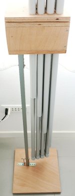
I complete the previous post with some photos of the project components: compression chamber, mmdTL rear acoustic load and subsonic resonance support.

The compression chamber is made of 15 mm plywood, a 115 x 130 x 210 mm parallelepiped open on the front side. The internal volume is 85 x 100 x 190 mm without acoustic absorber.

On the upper and lower side of the compression chamber there are 12 + 12 holes for fixing the mddTL rear acoustic load. The central holes are the outputs for the waveguides and protrude inside for 25 mm. The lateral holes are acoustically isolated from the compression chamber.

The mddTL rear acoustic load is made of two parts: the lower one fixed directly to the compression chamber, the upper one fixed to a 130 x 210 x 15 mm plywood flange with 12 holes aligned with those of the compression chamber. The 8 waveguides are made of rigid PVC pipes for reading systems with an external diameter of 25 mm. The fittings are pieces of flexible sheath for 25 mm electrical systems, 120 mm long.
The waveguide exits from the central hole on the lower side of the compression chamber, the first part is 890 mm long and with a flexible fitting it turns 180 degrees, re-enters the side hole and passes through the compression chamber to the upper side. There are 4 U-shaped waveguides. In the remaining 4 side holes the end parts of the four upper U-shaped waveguides are fixed.

4 U-shaped waveguides 550 mm long are fixed to the upper flange, connected with flexible sheath. The waveguide exit is in the central holes and re-enters the side holes. In the remaining 4 side holes the end parts of the four lower U-shaped waveguides are fixed.

Adhesive polyurethane foam used to insulate air conditioning pipes is glued between the compression chamber and the upper flange. The flange is firmly fixed with 8 screws to the upper side of the compression chamber. The passage of the waveguides through the compression chamber greatly reduces vibrations compared to previous prototypes such as cl08a2 with guides over 2 meters long.

A steel L-bracket fixes the compression chamber to a 20 x 20 mm square aluminum profile. The other side of the stand is fixed with other L-brackets to a 340 x 340 x 15 mm square base. In the base are applied 3 rubber feet, two in the rear edges and one in the front at a distance from the sides of 130 and 210 mm. The profile is fixed to the base near the front foot.
The elasticity of the steel bracket allows the stand to oscillate at subsonic frequency. The compression chamber is acoustically isolated from the floor in the audio band.


The front is a 130 x 130 x 4 mm plywood panel already used in the cl0800 prototype. The connection wire passes through this panel, the system is very convenient for easily replacing the driver. The wire that reaches the negative pole of the driver passes behind the spoke of the basket to avoid creating a loop with ferromagnetic material inside.
The construction difficulty is medium but does not require carpentry equipment. The project is more complex than a parallelepiped with bass-reflex but simpler than a horn loading. All the material is easily available and costs less than 100 euros, including the drivers.
link
https://www.claudiogandolfi.it
https://www.claudiogandolfi.it/cl08fr.html
The compression chamber is made of 15 mm plywood, a 115 x 130 x 210 mm parallelepiped open on the front side. The internal volume is 85 x 100 x 190 mm without acoustic absorber.
On the upper and lower side of the compression chamber there are 12 + 12 holes for fixing the mddTL rear acoustic load. The central holes are the outputs for the waveguides and protrude inside for 25 mm. The lateral holes are acoustically isolated from the compression chamber.
The mddTL rear acoustic load is made of two parts: the lower one fixed directly to the compression chamber, the upper one fixed to a 130 x 210 x 15 mm plywood flange with 12 holes aligned with those of the compression chamber. The 8 waveguides are made of rigid PVC pipes for reading systems with an external diameter of 25 mm. The fittings are pieces of flexible sheath for 25 mm electrical systems, 120 mm long.
The waveguide exits from the central hole on the lower side of the compression chamber, the first part is 890 mm long and with a flexible fitting it turns 180 degrees, re-enters the side hole and passes through the compression chamber to the upper side. There are 4 U-shaped waveguides. In the remaining 4 side holes the end parts of the four upper U-shaped waveguides are fixed.
4 U-shaped waveguides 550 mm long are fixed to the upper flange, connected with flexible sheath. The waveguide exit is in the central holes and re-enters the side holes. In the remaining 4 side holes the end parts of the four lower U-shaped waveguides are fixed.
Adhesive polyurethane foam used to insulate air conditioning pipes is glued between the compression chamber and the upper flange. The flange is firmly fixed with 8 screws to the upper side of the compression chamber. The passage of the waveguides through the compression chamber greatly reduces vibrations compared to previous prototypes such as cl08a2 with guides over 2 meters long.
A steel L-bracket fixes the compression chamber to a 20 x 20 mm square aluminum profile. The other side of the stand is fixed with other L-brackets to a 340 x 340 x 15 mm square base. In the base are applied 3 rubber feet, two in the rear edges and one in the front at a distance from the sides of 130 and 210 mm. The profile is fixed to the base near the front foot.
The elasticity of the steel bracket allows the stand to oscillate at subsonic frequency. The compression chamber is acoustically isolated from the floor in the audio band.
The front is a 130 x 130 x 4 mm plywood panel already used in the cl0800 prototype. The connection wire passes through this panel, the system is very convenient for easily replacing the driver. The wire that reaches the negative pole of the driver passes behind the spoke of the basket to avoid creating a loop with ferromagnetic material inside.
The construction difficulty is medium but does not require carpentry equipment. The project is more complex than a parallelepiped with bass-reflex but simpler than a horn loading. All the material is easily available and costs less than 100 euros, including the drivers.
link
https://www.claudiogandolfi.it
https://www.claudiogandolfi.it/cl08fr.html
Attachments
For listening at moderate levels it will work.
Its still a small driver.
Did one with low tuned reflex and it sounds great. Also extends to 60hz but sounds lower.
https://www.diyaudio.com/community/...loudspeaker-sandwich-cone.402917/post-7719825

Its still a small driver.
Did one with low tuned reflex and it sounds great. Also extends to 60hz but sounds lower.
https://www.diyaudio.com/community/...loudspeaker-sandwich-cone.402917/post-7719825
Years ago I saw a concert of the Blue Man Group, they also use PVC waveguides but larger. Making them with PVC is simple and cheap.
Now I use multiple waveguides to make the acoustic load independent from the driver used. With multiple waveguides you also have coherent, delayed and spatially distributed emission points. In addition to PVC I have tried aluminum, cardboard, honeycomb polypropylene.
Now I use multiple waveguides to make the acoustic load independent from the driver used. With multiple waveguides you also have coherent, delayed and spatially distributed emission points. In addition to PVC I have tried aluminum, cardboard, honeycomb polypropylene.
CL13FR: Ciare HX 135 universal full range (2024 11)
The CL13FR project was born to verify if the mddTL rear acoustic load of the CL08FR project is universal, that is, directly adaptable to other drivers regardless of the TS parameters.
In previous projects I followed my rule of thumb to have the total section of the multiple waveguides of the mddTL rear acoustic load similar to the surface of the driver cone. With this rule, to use a larger speaker it is necessary to build a new acoustic load, I almost always preferred to continue using the 3FE25 from Faital-Pro, its sound pressure is sufficient for my needs (max. 90 dB). The section of the mddTL rear acoustic load limits the maximum acoustic pressure, with high pressures turbulent motions should be generated that would worsen the quality of reproduction, I did not do tests at high volumes. The mddTL rear acoustic load of the CL08FR project must work equally well with a larger driver at the same acoustic pressures.

I built a 160 x 160 mm frame out of 15 mm plywood to fit larger drivers to the mddTL rear acoustic load of the CL08FR project. As a driver I used a pair of Ciare HX135s, now out of production, of excellent quality. At the time of purchase, ten years ago, the price of the HX135 was about ten times the price of the 3FE25.

The transplant gave excellent results, the higher quality of the HX135 driver is perceived from the first listen. On the same frame I mounted both the 3FE25 driver and a Ciare HX101 driver, with these drivers I do not have measurements because of the rush to try the HX135. In any case, even the cheaper 3FE25 driver is fun to listen to and returns a wide and detailed sound image. With the Ciare HX101 the bass improves and the distortion decreases and with the HX135 you have a further reinforcement on the bass and further decreases the distortion.
These tests indicate that the mddTL rear acoustic load adapts well to drivers with different characteristics. It is especially sensitive to the quality of the driver, the listening environment and the lack of spurious vibrations. Its design is independent of the TS parameters and I can continue to call it universal full range.
https://www.claudiogandolfi.it
https://www.claudiogandolfi.it/cl08fr.html#13
The CL13FR project was born to verify if the mddTL rear acoustic load of the CL08FR project is universal, that is, directly adaptable to other drivers regardless of the TS parameters.
In previous projects I followed my rule of thumb to have the total section of the multiple waveguides of the mddTL rear acoustic load similar to the surface of the driver cone. With this rule, to use a larger speaker it is necessary to build a new acoustic load, I almost always preferred to continue using the 3FE25 from Faital-Pro, its sound pressure is sufficient for my needs (max. 90 dB). The section of the mddTL rear acoustic load limits the maximum acoustic pressure, with high pressures turbulent motions should be generated that would worsen the quality of reproduction, I did not do tests at high volumes. The mddTL rear acoustic load of the CL08FR project must work equally well with a larger driver at the same acoustic pressures.
I built a 160 x 160 mm frame out of 15 mm plywood to fit larger drivers to the mddTL rear acoustic load of the CL08FR project. As a driver I used a pair of Ciare HX135s, now out of production, of excellent quality. At the time of purchase, ten years ago, the price of the HX135 was about ten times the price of the 3FE25.
The transplant gave excellent results, the higher quality of the HX135 driver is perceived from the first listen. On the same frame I mounted both the 3FE25 driver and a Ciare HX101 driver, with these drivers I do not have measurements because of the rush to try the HX135. In any case, even the cheaper 3FE25 driver is fun to listen to and returns a wide and detailed sound image. With the Ciare HX101 the bass improves and the distortion decreases and with the HX135 you have a further reinforcement on the bass and further decreases the distortion.
These tests indicate that the mddTL rear acoustic load adapts well to drivers with different characteristics. It is especially sensitive to the quality of the driver, the listening environment and the lack of spurious vibrations. Its design is independent of the TS parameters and I can continue to call it universal full range.
https://www.claudiogandolfi.it
https://www.claudiogandolfi.it/cl08fr.html#13
@claudiogan I think you should make a set of your pipe speakers out of copper pipe. It would be the coolest steam punk loudspeaker ever! Make the loudspeaker box look like a boiler with a VU meter that looks like a pressure valve.
CL10FR universal full range (2024 11)


I adapted the Ciare HX101 driver, now out of production, to the 160 x 160 mm 15 mm plywood frame of the CL13FR project. At the time of purchase, ten years ago, the price of the HX101 was about five times the price of the 3FE25.

The CL10FR project (HX101 driver) compared to the CL13FR project (HX135 driver) has a slightly higher distortion and a reduced frequency response. Difference justified by the difference in costs, the HX101 driver cost about half the HX135 driver.
The measurements indicate that the mddTL rear acoustic load of the CL13FR project also adapts well to the HX101 driver. Sound reproduction is influenced mainly by the quality of the driver, the listening environment and the lack of spurious vibrations.
link: https://www.claudiogandolfi.it/cl08fr.html#10
I adapted the Ciare HX101 driver, now out of production, to the 160 x 160 mm 15 mm plywood frame of the CL13FR project. At the time of purchase, ten years ago, the price of the HX101 was about five times the price of the 3FE25.
The CL10FR project (HX101 driver) compared to the CL13FR project (HX135 driver) has a slightly higher distortion and a reduced frequency response. Difference justified by the difference in costs, the HX101 driver cost about half the HX135 driver.
The measurements indicate that the mddTL rear acoustic load of the CL13FR project also adapts well to the HX101 driver. Sound reproduction is influenced mainly by the quality of the driver, the listening environment and the lack of spurious vibrations.
link: https://www.claudiogandolfi.it/cl08fr.html#10
CL08FRb universal full range (2024 11)

I adapted the Faital-Pro 3FE25 driver to the 160 x 160 mm 15 mm plywood frame of the CL13FR project. The distances between the sides of the front panel and the center of the driver are in golden ratio, 60 and 100 mm.

The CL08FRb project (3FE25 driver) compared to the CL13FR project (HX135 driver) has a higher distortion and a reduced frequency response. Difference justified by the difference in costs, the HX135 driver cost about 10 times the 3FE25 driver, even the cheaper 3FE25 is fun to listen to and returns a wide and detailed sound image.
Measurements indicate that the mddTL rear acoustic load of the CL13FR design also fits well with the 3FE25 driver. Sound reproduction is influenced above all by the quality of the driver, the listening environment and the lack of spurious vibrations.
link: https://www.claudiogandolfi.it/cl08fr.html#08b
I adapted the Faital-Pro 3FE25 driver to the 160 x 160 mm 15 mm plywood frame of the CL13FR project. The distances between the sides of the front panel and the center of the driver are in golden ratio, 60 and 100 mm.
The CL08FRb project (3FE25 driver) compared to the CL13FR project (HX135 driver) has a higher distortion and a reduced frequency response. Difference justified by the difference in costs, the HX135 driver cost about 10 times the 3FE25 driver, even the cheaper 3FE25 is fun to listen to and returns a wide and detailed sound image.
Measurements indicate that the mddTL rear acoustic load of the CL13FR design also fits well with the 3FE25 driver. Sound reproduction is influenced above all by the quality of the driver, the listening environment and the lack of spurious vibrations.
link: https://www.claudiogandolfi.it/cl08fr.html#08b
UFR universal full range (2024 11)
The CL08FR project is the result of the simplification of the MDD CL08A2 project, a single driver per channel, reduced length of the rear acoustic load mddTL (2880 mm - 29 Hz), direct directional emission, elimination of the omnidirectional acoustic diffractor (mddOmni). The subsonic resonance support with an asymmetric base remains, the anti-Haas effect remains, spurious resonances are reduced with the waveguides constrained to the compression chamber at multiple points.
The mddTL rear acoustic load project is independent of the TS parameters, it adapts well to drivers with different characteristics (universal). The only parameter used is the speed of sound (341 m/sec) to calculate the resonances of the individual waveguides. The mddTL acoustic load can be considered neutral with respect to the driver and listening environment. On a 160 x 160 mm frame I tested three different drivers: Ciare HX135 (13 cm), Ciare HX101 (10 cm), Faital_pro 3FE25 (8 cm). The section of the waveguides does not influence the frequency response, with the same sound pressure in the compression chamber it does not matter if the driver has an 8, 10 or 13 cm cone. At high SPL turbulences could be activated that degrade the quality of the reproduction, I have never found myself in these conditions, I listen in an apartment building and reach a maximum of 90 dB.

In the graph I compare the distortion of the three different drivers: Ciare HX135 (red), Ciare HX101 (blue), Faital_Pro 3FE25 (green). The sound reproduction is sensitive above all to the quality of the driver and the lack of spurious vibrations. Increasing the surface area of the driver reduces the distortion.

Ciare HX135 (red), Ciare HX101 (blue), Faital_Pro 3FE25 (green). The frequency response changes little between the three drivers, the irregularities are caused by the interaction with the listening environment.

Ciare HX135 (red), Ciare HX101 (blue), Faital_Pro 3FE25 (green). The step responses are similar.
The main advantages of a UFR (universal full range) cabinet are:
1 - it does not introduce any resonances in the frequency response;
2 - it emits a series of secondary waves that are coherent, delayed and symmetrical for the two channels that optimize the interaction with the listening environment;
3 - it is built with cheap and easily available materials;
4 - the design does not depend on the TS parameters but only on the speed of sound in the air.
The design is simple. The compression chamber is a parallelepiped with the driver fixed on the front side. On the upper and lower side there are 12 + 12 holes in which to fix the 8 waveguides. A series of waveguide lengths is: 1570, 1712, 1867, 2036, 2221, 2422, 2641, 2880 mm, can be increased or decreased in proportion. A support is fixed to the lower side of the box, the elasticity must be adjusted by trial and error to the weight and geometry of the system so that it oscillates at about 1 Hz, the oscillations must be visible.
By carefully fixing the waveguides to the compression chamber, by properly making the subsonic resonance support, you can make the most of the potential of a full-range driver. The construction is not for beginners, the numerous components can become a source of spurious vibrations that worsen the quality of the reproduction.
link: https://www.claudiogandolfi.it/cl08fr.html#ufr
The CL08FR project is the result of the simplification of the MDD CL08A2 project, a single driver per channel, reduced length of the rear acoustic load mddTL (2880 mm - 29 Hz), direct directional emission, elimination of the omnidirectional acoustic diffractor (mddOmni). The subsonic resonance support with an asymmetric base remains, the anti-Haas effect remains, spurious resonances are reduced with the waveguides constrained to the compression chamber at multiple points.
The mddTL rear acoustic load project is independent of the TS parameters, it adapts well to drivers with different characteristics (universal). The only parameter used is the speed of sound (341 m/sec) to calculate the resonances of the individual waveguides. The mddTL acoustic load can be considered neutral with respect to the driver and listening environment. On a 160 x 160 mm frame I tested three different drivers: Ciare HX135 (13 cm), Ciare HX101 (10 cm), Faital_pro 3FE25 (8 cm). The section of the waveguides does not influence the frequency response, with the same sound pressure in the compression chamber it does not matter if the driver has an 8, 10 or 13 cm cone. At high SPL turbulences could be activated that degrade the quality of the reproduction, I have never found myself in these conditions, I listen in an apartment building and reach a maximum of 90 dB.
In the graph I compare the distortion of the three different drivers: Ciare HX135 (red), Ciare HX101 (blue), Faital_Pro 3FE25 (green). The sound reproduction is sensitive above all to the quality of the driver and the lack of spurious vibrations. Increasing the surface area of the driver reduces the distortion.
Ciare HX135 (red), Ciare HX101 (blue), Faital_Pro 3FE25 (green). The frequency response changes little between the three drivers, the irregularities are caused by the interaction with the listening environment.
Ciare HX135 (red), Ciare HX101 (blue), Faital_Pro 3FE25 (green). The step responses are similar.
The main advantages of a UFR (universal full range) cabinet are:
1 - it does not introduce any resonances in the frequency response;
2 - it emits a series of secondary waves that are coherent, delayed and symmetrical for the two channels that optimize the interaction with the listening environment;
3 - it is built with cheap and easily available materials;
4 - the design does not depend on the TS parameters but only on the speed of sound in the air.
The design is simple. The compression chamber is a parallelepiped with the driver fixed on the front side. On the upper and lower side there are 12 + 12 holes in which to fix the 8 waveguides. A series of waveguide lengths is: 1570, 1712, 1867, 2036, 2221, 2422, 2641, 2880 mm, can be increased or decreased in proportion. A support is fixed to the lower side of the box, the elasticity must be adjusted by trial and error to the weight and geometry of the system so that it oscillates at about 1 Hz, the oscillations must be visible.
By carefully fixing the waveguides to the compression chamber, by properly making the subsonic resonance support, you can make the most of the potential of a full-range driver. The construction is not for beginners, the numerous components can become a source of spurious vibrations that worsen the quality of the reproduction.
link: https://www.claudiogandolfi.it/cl08fr.html#ufr
These look like super interesting explorations and it would be fun to try one out.
- Is there an overall "best-sounding" configuration you've landed upon? I don't mind build complexity... so if I'm going to make one, I'm happy to make it a challenging one.
- Any chance you could make simple sketches with dimensions for the pieces of that configuration? To be honest, I found your descriptions a little confusing to follow!
- For the flexy 180 degree parts, how are you determining the length?
- I have easy access to the FaitalPRO 3FE25, and the 3FE22. Are you aware of another driver that's easy to find in the USA that should sound noticeably better, meaning, more comparable to the unavailable Ciare drivers you tried?
Cheers!
Hi dayneger, thanks for your attention to my project.
My descriptions are confusing for two reasons.
1 My posts are written in Italian and translated with Google Translator, I am not able to optimize the translation.
2 My projects normally have an average life of a few months, I provide details only if someone is interested and requests it.
The best sound is from the CL13FR prototype, thanks to the Ciare HX-135 speakers that cost 10 times the Faital-Pro 3FE25. In the projects of this thread you can use any driver, even recovered from old equipment, it is not necessary to know the TS parameters. Drivers with low distortion and high efficiency are preferable.
The series of lengths: 1570, 1712, 1867, 2036, 2221, 2422, 2641, 2880 mm, is calculated with an Excel sheet. In the post https://www.diyaudio.com/community/...onal-single-drive.342677/page-10#post-7376688 and following I explain the formulas. If requested I can provide further information.
I will not make drawings for now, I have already planned a new configuration of the waveguides, I will try it in the next few weeks.
For those who want to make a replica I will summarize the most important points.
a) The series of lengths of the 8 waveguides can be increased or decreased in proportion. If the length increases the response to low frequencies extends, the construction becomes more complicated and also increases the possibility of spurious vibrations.
b) The diameter of the 8 waveguides, 25 mm, can be reduced or increased to use available material. A reduced section limits the maximum SPL, I work with low powers so I have never come close to the maximum manageable sound pressure.
c) The 15 mm plywood compression chamber with external dimensions 130 x 130 x 210 mm is suitable for the Faital-Pro 3FE25 driver. I recommend a chamber with larger dimensions 160 x 160 x 260 mm, to use drivers up to 5” and increase the space for the waveguides.
d) The support bracket must be fixed between the center of gravity of the compression chamber and the front, the point is to be found by subsequent attempts. If the bracket is in a position too advanced, the weight of the PVC waveguides could deform it.
https://www.claudiogandolfi.it/cl08fr.html#13
Did you try the same project with a bigger fullrange driver like 20cm/8inch?
Could imagine that the pipes then get more serious engaged in the sound (more movement of air)
Could imagine that the pipes then get more serious engaged in the sound (more movement of air)
hello Freedom666
if I had an 8” driver I would try it in a 21 x 21 x 34 cm compression chamber. I would leave everything else unchanged and check the operation at high volumes.
Alternatively, knowing how to use a simulation software, you could check at what sound levels turbulent motions would be triggered inside the waveguides.
For the moment, these two things are not planned.
Were you thinking about something like the SB Acoustics SB20FRPC30?Did you try the same project with a bigger fullrange driver like 20cm/8inch?
Could imagine that the pipes then get more serious engaged in the sound (more movement of air)
If I had it I would make a prototype with a 23 x 23 x 37 cm compression chamber, in 20 mm plywood. I think it would be a fun system to listen to.Were you thinking about something like the SB Acoustics SB20FRPC30?
- Home
- Loudspeakers
- Full Range
- CL08FR universal full range (2024 09)