In triode connection the screen grid (g2) at the pin 4 is connected directly or via small resistor to plate at the pin 3.
In UL-connection the screen grid is connected to UL-tap of the output transformer, directly or via small resistor.
The plate and screen grid of a tube should be connected to the same primary halve of the output tube.
In UL-connection the screen grid is connected to UL-tap of the output transformer, directly or via small resistor.
The plate and screen grid of a tube should be connected to the same primary halve of the output tube.
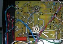
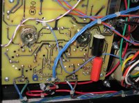
There are some pics and a schematic here may help you to wire back to original ultra-linear mode.
")
Thank you Artosolo and Koonw. Especially for the schematic.
Still unsure quite what to do.
I could not attach the photos I have. Got an error message saying that the security token was missing.
Disconnect all wiring or links for triode mode.
The green and brown wire lead from the OPT should be connected back to pcb as shown if they're detached but may still on pcb. These wire lead maybe just links at these point and not use in triode mode. Take all cautions as there is high voltage.
Attachments
Last edited:
Thank you Artosolo and Koonw. Especially for the schematic.
Still unsure quite what to do.
I could not attach the photos I have. Got an error message saying that the security token was missing.
It's a persistent error, but it usually means your files are too large.

Let's try this.
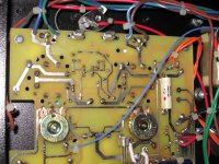
Koonw, so these links need to be cut?
That is correct these links need to be cut or better to desolder them, you can reuse these links for ultra-linear mode.
Last edited:
Koonw,
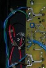
Is possible to make the image post 5 a little larger? So I can see how the links are positioned? (From 90 degree angle to diagonally is what I understanding)
Thanks
Attachments
In triode connection the screen grid (g2) at the pin 4 is connected directly or via small resistor to plate at the pin 3.
In UL-connection the screen grid is connected to UL-tap of the output transformer, directly or via small resistor.
The plate and screen grid of a tube should be connected to the same primary halve of the output tube.
Put a 220R 2watt resistor in series with screen grid and connect to ultra linear transformer tap. If you don't use a resistor if the amp is overdriven too much current goes through screen grid and can damage the valve.

Okay got the amplifier links oriented back to the ultra linear position, powered up the amplifier set the bias for all the tubes except the first power tube on the right looking at the amp from the front. The bias pot for that tube seems to have no effect when turned, on the visual LED indicator. What's happening here?
On the other hand, I thank God that none of the magic smoke came out, no hum ...
and when playing music put a smile on our faces. There was a slight thump at turn off on through the speaker on the right side.the same side the tube that couldn't be adjusted. But, for our brief listening it was just "noticeable ".
Last edited:
The bias pots are adjusting the idle current for each output tube. There's a detect circuit that flips an led on when its on the verge of too much bias current.
The adjust range is not great, to keep from biasing too hot or cold. Try swapping tube locations. If you can't properly adjust bias for that tube in the new position, then the tube itself is out of spec for what CJ expected. If it biases up fine in the new position I'd then suspect the bias adjust circuit for that original position.
The adjust range is not great, to keep from biasing too hot or cold. Try swapping tube locations. If you can't properly adjust bias for that tube in the new position, then the tube itself is out of spec for what CJ expected. If it biases up fine in the new position I'd then suspect the bias adjust circuit for that original position.
If I were to guess, I'd say the bias circuit itself is working properly and it's the detect circuit that is broken. Here's what you can do to test this. Place the pos meter probe on the cathode of the tube socket in question, and the neg probe on ground. Set the meter to read millivolts. Turn the bias pot and see if it changes the reading on the meter. If it does, make the voltage reading be the same as on another good socket after biasing that socket in the proper manner using the led indicator.

- Status
- This old topic is closed. If you want to reopen this topic, contact a moderator using the "Report Post" button.
- Home
- Amplifiers
- Tubes / Valves
- CJ MV60 triode to ultralinear