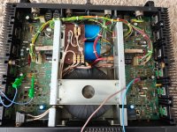
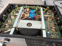
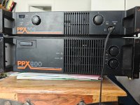
Here is a 1990 circa Citronic PPX300 Lateral MOSFET amplifier, made in the UK!. As some will know these PPX amps are very well built and reliable. (The bigger versions have drain fuses on each MOSFETS)
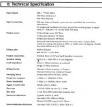
100 watts @ 8 ohms per channel, 500VA transformer, three pairs of lateral MOSFETS per channel, 2x10,000uF filter caps, headphone output via dropping 68ohm large resistors and caps (big ceramic resistors in pic) No relays. DC protection via TRIAC crowbar. Also includes some sort of VI limiting circuit to protect the gates? Looks like there is drain resistors for each MOSFET? Help limit current instead of fuses like the bigger models? Dead silent main outputs and headphone outputs
All seems original. Just going through a little refurbishment. Nearly all capacitors are still in tolerance except for the DC blocking input caps around the level pots. Changed them from 10uf to 100uf for a lower high pass frequency. Changed the feedback DC blocking cap to 470uf. There is a few tantalum caps but they measure spot on.
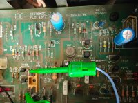
Bias was a bit hit and miss. The bias pots have an unknown value. On the case of both pots there is melted part, I guess to prevent movement? Little sticker on top to prevent dust ingress. Both pots fell to pieces when I removed them. I tried a 470 ohm pots as a replacement but got very little movement in bias so I tried a much high resistance 5k pots for now. Bias quite sensitive to these high resistance pots. Higher resistance increases bias, lower resistance lowers bias. Set bias at 150ma. The bias transistor gets rather hot though on both sides no matter the bias current. Too hot to touch, approx 50c, TR7/TR17 2n5416 in pic .
There also seems to be a Thermistor (TH1) connected between P and N gate resistors. Anyone know why?
The dropping resistors for the opamp 15v supplies will need replacing, Heat cracking 1.8K I think.
Subjective sound qualities... Bass very good, top end best I have ever heard. Very smooth.
Does anyone have a schematic for the PPX300? I have a schematics for the PPX900 but there is differences and board printed component numbers are different on this 300. Thanks.
100 watts @ 8 ohms per channel, 500VA transformer, three pairs of lateral MOSFETS per channel, 2x10,000uF filter caps, headphone output via dropping 68ohm large resistors and caps (big ceramic resistors in pic) No relays. DC protection via TRIAC crowbar. Also includes some sort of VI limiting circuit to protect the gates? Looks like there is drain resistors for each MOSFET? Help limit current instead of fuses like the bigger models? Dead silent main outputs and headphone outputs
All seems original. Just going through a little refurbishment. Nearly all capacitors are still in tolerance except for the DC blocking input caps around the level pots. Changed them from 10uf to 100uf for a lower high pass frequency. Changed the feedback DC blocking cap to 470uf. There is a few tantalum caps but they measure spot on.
Bias was a bit hit and miss. The bias pots have an unknown value. On the case of both pots there is melted part, I guess to prevent movement? Little sticker on top to prevent dust ingress. Both pots fell to pieces when I removed them. I tried a 470 ohm pots as a replacement but got very little movement in bias so I tried a much high resistance 5k pots for now. Bias quite sensitive to these high resistance pots. Higher resistance increases bias, lower resistance lowers bias. Set bias at 150ma. The bias transistor gets rather hot though on both sides no matter the bias current. Too hot to touch, approx 50c, TR7/TR17 2n5416 in pic .
There also seems to be a Thermistor (TH1) connected between P and N gate resistors. Anyone know why?
The dropping resistors for the opamp 15v supplies will need replacing, Heat cracking 1.8K I think.
Subjective sound qualities... Bass very good, top end best I have ever heard. Very smooth.
Does anyone have a schematic for the PPX300? I have a schematics for the PPX900 but there is differences and board printed component numbers are different on this 300. Thanks.
Attachments
I'm afraid I can only give your thread a bump! Unfortunately, this member of the original PPX Series seems to be the one lacking a published schematic.
The Citronic PPX-300 power amp was made in the UK to a very high standard - not to be confused with the more modern Citronic PPX300 equivalent.
The original PPX Series amps were solid, well constructed and conservatively rated. When the PPX-300 says 150 W per channel into 4 ohm, one can be sure that this is a continuous rating commensurate with punishing Disco use.
I've got an ex-Disco Citronic PPX-450 (225 W per channel into 4 ohm) sitting in a flight case in my garage. They don't make them like this anymore, it's built like a tank!

You are right there. They are over engineered. Very good standard of build. The transformer is made by Holden & Fisher.
The only thing I've noticed is the bias pots gets a bit warm (approx 48 degrees) I think that's why the old pots broke up when I removed them. The bias circuit seems to be a bit different on what i've seen on other MOSFET amps. The bias transistor 2n5416 also gets rather hot, I think they specified this transistor because of heat (metal can). I need to find some better pots and maybe a resistor across the pots to dissipate the heat a bit better.
The thermistor seems to be added on at a later date of runs. Looks like some sort of limiting between the gates.
You may want to replace it with a 1K~2K pot. That will give you better control.I tried a 470 ohm pots as a replacement but got very little movement in bias so I tried a much high resistance 5k pots for now. Bias quite sensitive to these high resistance pots. Higher resistance increases bias, lower resistance lowers bias. Set bias at 150ma. The bias transistor gets rather hot though on both sides no matter the bias current. Too hot to touch, approx 50c, TR7/TR17 2n5416 in pic .
TR7 and the associate transistor are for current limiting of the mosfet gate drive.
They should not be hot. That indicates a fault.
As for the Thermistor TH1, it's actually a Varistor.
Usually a 10~12V zener is used to limit the gate voltage.
I suggest you check all the power mosfets.
Perhaps one or more is damaged.
Regards
Mike
AmpsLab
Sorry, I meant TR9 and 5 that get hot (labeled on the PPX900 schematic) These are labelled TR7 and 17 on the PPX300....
On the PPX900. These two transistors are heatsinked. I guess they thought it was not needed in the PPX300 after studying other pics of PPX300's
On the PPX900. These two transistors are heatsinked. I guess they thought it was not needed in the PPX300 after studying other pics of PPX300's
Looks like the 2nd stage is damaged.
I would replace all the transistors there as well as in the input differential.
Also, check all resistors and diodes.
High current is passing through TR7 & 17 which should not be.
I would replace all the transistors there as well as in the input differential.
Also, check all resistors and diodes.
High current is passing through TR7 & 17 which should not be.
Power and distortion tests work out all fine.
DC offset approx 1mV on both channels.
Nothing tests bad. I put heatsinks on the 2n5416 which helped. I'm guessing its heat coming from nearby opamp supply resistors. Opamp supplies are 15v from 15v zeners and 1.8K resistors. I have changed the resistors to 3 watts and lifted off the board as the old ones were cracking.
- Home
- Amplifiers
- Solid State
- Citronic PPX300 (old type)