I'm adding my final updates to my Citation 2024 amp'
1. No change to the main PCB.
2. Speaker Dethumper PCB , Resistor R1 changed to a 200k pot by drilling two holes for the pot.. The cap C1 changed to 220uF. Time can be set from 48-0 seconds.
3. New Gerber rev 4 files for the speaker PCB with Gerber files is attached below.
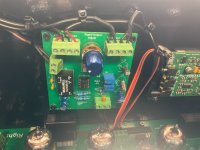
4. Power supply PCB changed to rev 15. C2, C4 changed to 1000uF 500VDC. Added a terminal block to add a choke of desired. L1 Chole is a 1H 600mA.
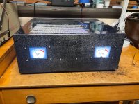
5. Optional two VU meter panels are interchangeable. One is analog VU meters, the other is a LCD Touchscreen. Both are fed off the 12 volt power supply and the left/right signals from the main PCB. All files for both versions are available in this post.
6. Also include with this post are all the schematics, Gerber assembly, BOM and photos.
7. My only request, is that if anybody does try this project to let me know how it works out for you. You are responsible for your changes.
8. Did look into upping the power from 30 to 60 watts. Decided not to do after looking at the original amp and it's wiring.
8. The amplifier has been running fine since August.
Enjoy... Happy Holidays
1. No change to the main PCB.
2. Speaker Dethumper PCB , Resistor R1 changed to a 200k pot by drilling two holes for the pot.. The cap C1 changed to 220uF. Time can be set from 48-0 seconds.
3. New Gerber rev 4 files for the speaker PCB with Gerber files is attached below.
4. Power supply PCB changed to rev 15. C2, C4 changed to 1000uF 500VDC. Added a terminal block to add a choke of desired. L1 Chole is a 1H 600mA.
5. Optional two VU meter panels are interchangeable. One is analog VU meters, the other is a LCD Touchscreen. Both are fed off the 12 volt power supply and the left/right signals from the main PCB. All files for both versions are available in this post.
6. Also include with this post are all the schematics, Gerber assembly, BOM and photos.
7. My only request, is that if anybody does try this project to let me know how it works out for you. You are responsible for your changes.
8. Did look into upping the power from 30 to 60 watts. Decided not to do after looking at the original amp and it's wiring.
8. The amplifier has been running fine since August.
Enjoy... Happy Holidays
Attachments
-
BOM.zip670.6 KB · Views: 73
-
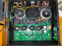 Case_topview.JPG720.3 KB · Views: 206
 -
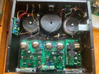
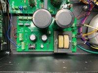 Pwr Supply.JPG748.2 KB · Views: 211
 -
 LCD Touchscreen reiew view.JPG698.1 KB · Views: 219
 -
 FrontView_clear cover.JPG787.1 KB · Views: 203
 -
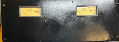 Frontview analog VU.JPG469.4 KB · Views: 204
 -
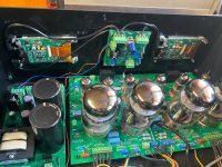
 Analog VU driver pcb.JPG674.5 KB · Views: 184
 -
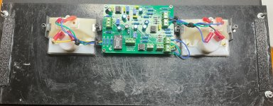 Backview_analog VU.JPG462.4 KB · Views: 213
 -
Schematics.zip656.8 KB · Views: 127
-
PDF.zip3.4 MB · Views: 955
-
Gerber_files.zip1.9 MB · Views: 485

Hi,
I like your amp and your VU meters. I see the schematic and the gerbers for the VU-meter board, but what exactly do I need from the gerber files to get PCB's made for example by JLCPCB? There are many files...
I want to use analog meters from "old" professional studio equipment.
Regards ,Gerrit
I like your amp and your VU meters. I see the schematic and the gerbers for the VU-meter board, but what exactly do I need from the gerber files to get PCB's made for example by JLCPCB? There are many files...
I want to use analog meters from "old" professional studio equipment.
Regards ,Gerrit
Yes, I just tried this and I was able to order the boards.
Regards, Gerrit
Regards, Gerrit
I see now that the VU meter BOM is a copy of the speaker protection BOM.
I would like to have a BOM for the VU meter. Otherwise I have to wait until I get the boards to start looking for parts.
Regareds, Gerrit
I would like to have a BOM for the VU meter. Otherwise I have to wait until I get the boards to start looking for parts.
Regareds, Gerrit
Here are the files you asked for. Sorry about the screw up....a senior moment
Attachments
Hi LMitchell,
Unfortunately your “Analog VU PCB Parts BOM Cost” still is for the SPEAKER, with a relay, etc.. I really don’t know what goes wrong, but I still hope you have it somewhere.
Do you have any comments regarding how to use the VU meter with analog meters. How about the jumpers, the uA meters used, etc..
Regards, Gerrit
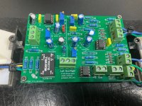
The VU driver section adds about 10db gain to the audio input signal. Signal input is the Audio IN terminal.
The two pots VR1, VR2 set the level for the driver section.
The jumpers are used to feed the signal to the VU meter section.
If you don't use or need the driver section the jumpers can be removed. (I use the driver section)
If you don't use the driver, then the audio input is the terminal block above the jumper comment.
Pots VR3,VR4 set the level for each meter.
The TN-43 meter can be bought from Amazon or Ebay.
Please let me know if you find any other mistakes or missing items.
Thanks for trying to building my project. Please let me know how you make out.
Be carefully with the voltages used in this build. Remember to us a shorting stick to discharge the caps.
Have fun.
LMitchell
Attachments
Hi Lmitchell,
Thanks for your update and BOM. I’m actually still working on another long term project, using KT150 tubes. I intend to add an external box with VU-meters as well as voltage / current meters to this project.
I will build you VU-meter board and I will try to use it with the VU-meters I bought years ago from a dismantled broadcast studio.
Regards, Gerrit
Found some bad traces on the LCD driver pcb. Pot was shorted out & pins 6 & 7 of the IC was shorted. Caused no signal gain on that signal. It was easier to redo the pcb . New files added.
Added a 1H @600ma choke to the power supply. It really improved the supply. Really quiet. You don't need the speaker dethumper pcb now.
Happy Holidays
Added a 1H @600ma choke to the power supply. It really improved the supply. Really quiet. You don't need the speaker dethumper pcb now.
Happy Holidays
Attachments


I am from the old school of "tubes should be seen and heard". Also minimises heat problems.
Have you considered a main board layout change that allows for tube installation on reverse side of pcb?
Have you considered a main board layout change that allows for tube installation on reverse side of pcb?
Maybe the alternative approach would be to install everthing except tubes on bottom. Creating top access (holes) for TP 1-3 and Adj pots.
Thanks for the info. Maybe I’ll try the idea next year. Basically it wouldn’t be that hard. I think the tubes , adj pots and test points could be on the top and all of the rest on the bottom. The only problem with this is if any of the components on the bottom of the board would be hard to troubleshoot or replace without removing the pcb.
I need some help. I’m not a tube expert. I got my citation to do 50 watts by changing the main to a higher secondary. BUT , I’m 2 volts short on the output to get to 60 watts. I don’t want to change the transformer because I’m at the limit of pcb mountable caps, 600v. My plate voltage on the KT88 is 510 and my plate voltage on my input stage is 210. I can stay at where I am , but I would really like to set to 60 watts.
can I increase the voltage gain of the first stage to get my 2 volts there. I can’t do anything with an input ac it’s at 117.
Thanks for any suggestions. Lee
can I increase the voltage gain of the first stage to get my 2 volts there. I can’t do anything with an input ac it’s at 117.
Thanks for any suggestions. Lee
Is it the output stage clipping at 50W or the driver stage? What do the power tube grid signals look like when you are at 50W output?
- Home
- Amplifiers
- Tubes / Valves
- Citation 2024 Final