Note the test points TP-1 and 2 on your schematic, with no input adjust
the pot for .008V between the test points.
I = .008/.27 = 29.6 mA
Aha, so now, Im back on track?
Regards// Lasse
Note the test points TP-1 and 2 on your schematic, with no input adjust
the pot for .008V between the test points.
I = .008/.27 = 29.6 mA
Hi,
no problems to reach 8 mV by adjusting the pot. The voltage on the output was +120mV
I compared with the good channel. It was hard to come below 15mV but the output was -32mV
regards//lasse
There is no feedback so that is a reasonable offset and good that you are
able to bias it up.
It would be good to have output stage voltages again.
I have a feeling that if you were to replace the VAS transistor it will work, there
were some odd voltages along the way but it is looking about right now.
If you are curious, you could drive the other good channel with your generator, load
it with 10 ohms, get comfortable with 5 to 10 Volts out and 100 to 1KHz drive.
Then attach a low power 100 ohm resistor to the good output and jump it to the
VAS collector in the bad side. See if you can get a clean 5 to 10V output from
the bad side - first no load. The output stage is ~unity gain follower so it should
just replicate the input but with higher current capability.
Otherwise put in a good VAS transistor and report voltages.
Hi,
[/B][/COLOR]I compared with the good channel. It was hard to come below 15mV but the output was -32mV
regards//lasse
15mV trying to bias it or offset on the output?
Are you saying that you can't get correct bias on the "good" channel?
There is no feedback so that is a reasonable offset and good that you are
able to bias it up.
It would be good to have output stage voltages again.
I have a feeling that if you were to replace the VAS transistor it will work, there
were some odd voltages along the way but it is looking about right now.
If you are curious, you could drive the other good channel with your generator, load
it with 10 ohms, get comfortable with 5 to 10 Volts out and 100 to 1KHz drive.
Then attach a low power 100 ohm resistor to the good output and jump it to the
VAS collector in the bad side. See if you can get a clean 5 to 10V output from
the bad side - first no load. The output stage is ~unity gain follower so it should
just replicate the input but with higher current capability.
Otherwise put in a good VAS transistor and report voltages.
Hi and once again, thanks for this exclusive remote one-on-one help!
Now to the 10000$-question: What transistor should I go for? This is a very common question on the boards, I´m sure you know and there is a lot of different advice out there.
My first test was to replace the pre-driver (is that the VAS?) with a MJE15034G and it didn't work out. A lot of strange voltages in the wrong places:
VAS Collector: -39V
Bias Emitter +34,8V Base +39V Collector +40V
Diff amp Bases +7,2V +0,3V Emitters +0,87V
Driver Q706 Base +34,8V Emitter +33,6V Collector -35,6V
Driver Q710 Base +34,7V Emitter +39V Collector +35,7V
Output Q3 Emitter +39V
Output Q4 collector +39V
REgards//lasse
15mV trying to bias it or offset on the output?
Are you saying that you can't get correct bias on the "good" channel?
No I didn't get below 15mV between Tp3 and 4 on the good side.
The -32mV was the output voltage.
Regards//lasse
No I didn't get below 15mV between Tp3 and 4 on the good side.
The -32mV was the output voltage.
Regards//lasse
So the bias is nearly twice what it should be.
These never had very low offset at the output so not too far off.
Do you think that its a good Idea to Install that new MJE-transistor again and see what happens?
Hi and once again, thanks for this exclusive remote one-on-one help!
Now to the 10000$-question: What transistor should I go for? This is a very common question on the boards, I´m sure you know and there is a lot of different advice out there.
My first test was to replace the pre-driver (is that the VAS?) with a MJE15034G and it didn't work out. A lot of strange voltages in the wrong places:
VAS Collector: -39V
Bias Emitter +34,8V Base +39V Collector +40V
Diff amp Bases +7,2V +0,3V Emitters +0,87V
Driver Q706 Base +34,8V Emitter +33,6V Collector -35,6V
Driver Q710 Base +34,7V Emitter +39V Collector +35,7V
Output Q3 Emitter +39V
Output Q4 collector +39V
REgards//lasse
I would do the test with the other channel, since we did get some strange readings.
Everyone calls it a VAS these days, but yes what is called the pre-driver on that schematic.
The repair manual calls that out as an RCA 40408 which makes sense since the reference
design also uses that.
I have an RCA Transistor manual and the 40408 is a 90V, .7A, 1W, 100 MHz, 40-200(max) hfe.
It is a metal can device and so will take more power than a similar modern plastic type. I would
use a KSC2690 or KSC2690A, here are the specs:
120V, 1.5A, 1.2W, 155 MHz, 35-105(typ), I would put a screw through the mount hole
with a copper, aluminum or steel washer as a heatsink but just leave it in the air not
through the board.
These parts are hfe graded with R, O, Y designations, any will work fine. See the data
sheet for info:
http://www.mouser.com/ds/2/149/KSC2690A-889454.pdf
I have 60 of these and can send you some.
The Diodes Inc. ZTX653 in a plastic TO92 case is also interesting and probably one of the
best matches - I'd use a metal tab heatsink against the flat side of the case.
100V, 175 MHz, 1W, 2A, 100 hfe
Other options are:
KSC2383 in TO92L
2SC5171 in TO-220 good amount of metal no heat sink needed.
I ran through several parametric transistor selectors and there are not a lot to
choose from. Many options have gone to surface mount.
MJE15034G is a much higher current/power device and is just not right there.
Do you think that its a good Idea to Install that new MJE-transistor again and see what happens?
NO
Hi and thanks for the feedback.
So, perhaps I was on the right track from the beginning? The pre-driver didnt feel well but I replaced it with the wrong device.....
See what happens when a amateur goes to action and orders transistors without knowing what he/she is doing.
I will order new transistors, based on your advice and availability here in Sweden.
Best Regards// Lasse
I have checked with the Swedish suppliers and the device you mention:
"The Diodes Inc. ZTX653 in a plastic TO92"
Is available.
Could it be a good opportunity to upgrade some other stuff (or, rather to order at the same time when I´m ordering the transistors) under consideration for replacement? The trimpots?
Regards//lasse
"The Diodes Inc. ZTX653 in a plastic TO92"
Is available.
Could it be a good opportunity to upgrade some other stuff (or, rather to order at the same time when I´m ordering the transistors) under consideration for replacement? The trimpots?
Regards//lasse
Hi again,
Believe it or not, but my Christmas-vacation starts today!! I have a lot of time-compensation to take out from earlier military exercises so...I have time to check things daytime.
And now, I checked the output voltage with a 50W, 10 ohms resistor attached.
35mV on the good channel
120mV on the not so good (yet)
But today, it was no problems, adjusting the bias down to 8mV on both channels.
Regards//lasse
Hi.
I have ordered a number of transistors but it really seems like that type of heat sink isnt available in Sweden.
Regards// Lasse
I have ordered a number of transistors but it really seems like that type of heat sink isnt available in Sweden.
Regards// Lasse
DIY TO-92 heatsink | Make:
I would heat shrink AND epoxy it in place to avoid having it fall off and short out something.
I would heat shrink AND epoxy it in place to avoid having it fall off and short out something.
Hi,
tomorrow I will install a new predriver, ZTX653, and see (and measure) what happens.
Will be back with results
Regards//lasse
tomorrow I will install a new predriver, ZTX653, and see (and measure) what happens.
Will be back with results
Regards//lasse
Hi,
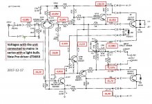
New pre-driver in place and new measurements:
http://www.diyaudio.com/forums/attachment.php?attachmentid=651713&stc=1&d=1513545733
Bias was 8mV as desired but the offset on the output was -345 mv, a bit high?
One voltage seems a bit strange and that is one of the bases on the diff-amp. Could that part be bad also?
Is it a good idea to replace the diff-amp with two ZTX653´s?
regards//lasse
Attachments
Yes that offset is far too high.
I would apply a sine wave in at 1 KHz, no load on the output and the light limiter still
in place. See if you can get a clean output of about 30V peak, 60V peak to peak, trying
to get within 5 volts of the rails.
I would apply a sine wave in at 1 KHz, no load on the output and the light limiter still
in place. See if you can get a clean output of about 30V peak, 60V peak to peak, trying
to get within 5 volts of the rails.
- Status
- Not open for further replies.
- Home
- Amplifiers
- Solid State
- Citation 12 trouble-new transistors