Can anyone explain the vacuum tube model parameters in CircuitMaker 2000. Below the original 12AU7 model.
*Vacuum Tube Triode (Audio freq.) pkg:VT-9 (A:1,2,3)(B:6,7,8)
.SUBCKT X12AU7 1 3 4
B1 2 4 I=((URAMP((V(2,4)/18)+V(3,4)))^1.5)/1151
C1 3 4 1.6E-12
C2 3 1 1.5E-12
C3 1 4 0.5E-12
R1 3 5 10E+3
D1 1 2 DX
D2 4 2 DX2
D3 5 4 DX
.MODEL DX D(IS=1.0E-12 RS=1.0)
.MODEL DX2 D(IS=1.0E-9 RS=1.0)
.ENDS X12AU7
I think that I have found some of the parameters:
?=Don't know
*Vacuum Tube Triode (Audio freq.) pkg:VT-9 (A:1,2,3)(B:6,7,8)
.SUBCKT X12AU7 1 3 4
B1 2 4 I=((URAMP((V(2,4)/18=my)+V(3,4)))^1.5=?)/1151=?
C1 3 4 1.6E-12 = Grid cap.
C2 3 1 1.5E-12 = Grid-Plate cap.
C3 1 4 0.5E-12 = Plate cap.
R1 3 5 10E+3 = Ri
D1 1 2 DX = ?
D2 4 2 DX2 = ?
D3 5 4 DX = ?
.MODEL DX D(IS=1.0E-12 RS=1.0) = ?
.MODEL DX2 D(IS=1.0E-9 RS=1.0) = ?
.ENDS X12AU7
*Vacuum Tube Triode (Audio freq.) pkg:VT-9 (A:1,2,3)(B:6,7,8)
.SUBCKT X12AU7 1 3 4
B1 2 4 I=((URAMP((V(2,4)/18)+V(3,4)))^1.5)/1151
C1 3 4 1.6E-12
C2 3 1 1.5E-12
C3 1 4 0.5E-12
R1 3 5 10E+3
D1 1 2 DX
D2 4 2 DX2
D3 5 4 DX
.MODEL DX D(IS=1.0E-12 RS=1.0)
.MODEL DX2 D(IS=1.0E-9 RS=1.0)
.ENDS X12AU7
I think that I have found some of the parameters:
?=Don't know
*Vacuum Tube Triode (Audio freq.) pkg:VT-9 (A:1,2,3)(B:6,7,8)
.SUBCKT X12AU7 1 3 4
B1 2 4 I=((URAMP((V(2,4)/18=my)+V(3,4)))^1.5=?)/1151=?
C1 3 4 1.6E-12 = Grid cap.
C2 3 1 1.5E-12 = Grid-Plate cap.
C3 1 4 0.5E-12 = Plate cap.
R1 3 5 10E+3 = Ri
D1 1 2 DX = ?
D2 4 2 DX2 = ?
D3 5 4 DX = ?
.MODEL DX D(IS=1.0E-12 RS=1.0) = ?
.MODEL DX2 D(IS=1.0E-9 RS=1.0) = ?
.ENDS X12AU7
Steen
mu is approximately 18
exact values of mu, gm and rp can be calculated, but I will have to get back to you on that
1151 sets the overall emission
^1.5 is the exponent, ie sets the rate of curvature of each grid curve
R1 is not rp. R1 is there to set grid current for 1ve grid voltage, which is modeled by a resistor and diode in series.
D1 is a diode to make sure current only flows from plate to cathode.
I am not sure why D2 is used.
Actually, I must correct myself. After doing the math I see that for this model mu is exactly 18 for all voltages.
gm is given by 1.5 * sqrt( Vp/18 + Vg) / 1151,
and rp is given by 1151 * 18 / ( 1.5 * sqrt( Vp / 18 + Vg ))
mu = gm * rp
The constant mu is an indication of the simplicity of the model, but it is quite useful anyway.
gm is given by 1.5 * sqrt( Vp/18 + Vg) / 1151,
and rp is given by 1151 * 18 / ( 1.5 * sqrt( Vp / 18 + Vg ))
mu = gm * rp
The constant mu is an indication of the simplicity of the model, but it is quite useful anyway.
Hello Robert
Thank's for your qiuck answer and explanation of the parameters of the model.
Now the values makes sense, so I can add new models.
I planning to add the 12AT7 and 6922 tube.
I know it's a simple model, but i works ok.
I have used CircuitMaker's build-in models and the simulation results are ok and within what you can exspect.
Steen")
Thank's for your qiuck answer and explanation of the parameters of the model.
Now the values makes sense, so I can add new models.
I planning to add the 12AT7 and 6922 tube.
I know it's a simple model, but i works ok.
I have used CircuitMaker's build-in models and the simulation results are ok and within what you can exspect.
Steen
Hi Steen
However, do not use that model for distorsion prevision, analisys or optimization.
Child's law, in fact, describes in a satisfactory way the real behavior of a triode only in case of great currents values and small potential differences Vak.
the posted figure shows the behavior of a real world triode in comparison to the model of Child, the fitting has been obtained imposing minimum error in case of Vgk=0 and -2. Curves obtained with Child’s law for different values of Vgk are simply translation of the one for Vgk=0. In real curves instead, current fixed, the slope of the curves decreases as Vak increases and we see a remarkable departure of the model from the real behavior.
Use Koren model for a better fitting
bye
Federico
curves from http://www.audiomatica.com/tubes/6sn7.htm
I know it's a simple model, but i works ok.
However, do not use that model for distorsion prevision, analisys or optimization.
Child's law, in fact, describes in a satisfactory way the real behavior of a triode only in case of great currents values and small potential differences Vak.
the posted figure shows the behavior of a real world triode in comparison to the model of Child, the fitting has been obtained imposing minimum error in case of Vgk=0 and -2. Curves obtained with Child’s law for different values of Vgk are simply translation of the one for Vgk=0. In real curves instead, current fixed, the slope of the curves decreases as Vak increases and we see a remarkable departure of the model from the real behavior.
Use Koren model for a better fitting
bye
Federico
curves from http://www.audiomatica.com/tubes/6sn7.htm
Attachments
Hi
Thank's again.
I won't use the CircuitMaker for any optimation and distortion analysis, only for schematic capture and some first hand operating point settings. I belive that if serious analysis is the quest, then PSpice is the answer.
P.S.: I'm new to Spice simulation.
Steen
Thank's again.
I won't use the CircuitMaker for any optimation and distortion analysis, only for schematic capture and some first hand operating point settings. I belive that if serious analysis is the quest, then PSpice is the answer.
P.S.: I'm new to Spice simulation.
Steen
Look at this thread in this forum:
http://www.diyaudio.com/forums/showthread.php?s=&threadid=56327
He wrote a program that allows you to create spice models from an image of the tube curves, for diodes and triodes. I used it, and it works well.
http://www.diyaudio.com/forums/showthread.php?s=&threadid=56327
He wrote a program that allows you to create spice models from an image of the tube curves, for diodes and triodes. I used it, and it works well.
Steen Bentzen said:Hi
Thank's again.
I won't use the CircuitMaker for any optimation and distortion analysis, only for schematic capture and some first hand operating point settings. I belive that if serious analysis is the quest, then PSpice is the answer.
P.S.: I'm new to Spice simulation.
Steen
Circuitmaker IS PSpice, speciffically, a front end to a speciffic variant of spice 3F4. There are very few simulators that do not use the spice engine.
Hi
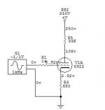
I have tried to make a model of the 6922 tube. I made a test setup with a 6922 from Electro Harmonics to verify the simulation result. In order to get the working point within 5V of the mesured value in the test setup, I have to set the "overall emission"
to a verry low value: 30 compared with an 12AU7 tube. Can this be true and is there a method calculate it?
*Vacuum Tube Triode (Audio freq.) pkg:VT-9 (A:1,2,3)(B:6,7,8)
.SUBCKT X6922 1 3 4
B1 2 4 I=((URAMP((V(2,4)/33)+V(3,4)))^1.5)/.30 ??
C1 3 4 3.3E-12
C2 3 1 3.0E-12
C3 1 4 1.8E-12
R1 3 5 3E+3
D1 1 2 DX
D2 4 2 DX2
D3 5 4 DX
.MODEL DX D(IS=1.0E-12 RS=1.0)
.MODEL DX2 D(IS=1.0E-9 RS=1.0)
.ENDS X6922
Se test setup
Attachments
There seems to be something wrong with your value of 30 ( or is it .30 ?)
the correct numbers can be calculated based on the equation the model is using, ie
I = (( Vp/u + Vg)^1.5) / K
to determine u and K just measure current with Vg = 0 at some convenient voltage, and Vp = say 100 V, then again at the same Vp and a different Vg, say -1 V.
(Of course this is with no load resistor or cathode resistor, by Vp I really mean Vpk )
With a bit of algebra the following equations are derived :
u = (Vp/Vg)*((I0/I1)^(2/3) -1) where I0 is the Vg = 0 current, and I1 is the other vg current
K = ((Vp/u)^1.5)/I0
example : from 6922 data sheet I see for Vp = 100 and Vg = 0 Ip = about 38mA. At Vp100 and Vg = -1 it is about 22 mA.
From this u = ( 100/ -1)*((.022/.038)^(2/3) -1 ) = 30.5 ( a good match with your 33)
and K = ((100/30.5)^1.5)/ .038 = 156.2
( much different than 30 or .30)
But there also seems to be something else wrong with this model, since it seems to clamp off the current at a value of 1/K, so I think there is a problem with nesting of the parentheses around the uramp statement, but I have not been able to figure out just what.
But there also seems to be something else wrong with this model, since it seems to clamp off the current at a value of 1/K, so I think there is a problem with nesting of the parentheses around the uramp statement, but I have not been able to figure out just what.
Actually there is a small problem with LTSpice that I forgot about, it does not like ^ for exponents, you must use ** instead. It does not give an error message, it just gives crazy results.
so for LTSpice users, change ^1.5 to **1.5, and change 30 to 156.2, and the model works OK
how I get tube spice models
Tekko :
I am not sure exactly what aspect of "doing the model" you mean, and maybe the question was for Steen and not me, so I hope I am not going off on a tangent here.
There are two basic ways you can add models.
1) Use models that are already written. Do a web search for tube spice models. Or do a search in this forum for tube spice models. Or go to WWW.DuncanAmps.com and look there.
2) Use an existing model type but supply your own parameters to match the particular tube you want.
Now if you absolutely want to use the Circuitmaker 2000 model that has been described here, then fine, but there are much better models out there. For models I do now I use Koren's model for plate current and Rydel's model for grid current, when I have data for grid current. Check out
http://digilander.libero.it/paeng/spice_models_for_vacuum_tubes.htm
and
http://www.normankoren.com/Audio/Tubemodspice_article.html
for more detailed information
Having decided on a model type, you need tube data to fit. You must either use data sheets or measure your own tubes.
For data sheets you can use a web search engine, use hard copy data books, or the best thing in my opinion is go to www.DuncanAmps.com again and use his Tube Data Sheet Locator. It has links to all the other best known tube data sites. If the TDSL doesnt point you to a data sheet then there probably is not one on the web. I got the downloadable version of TDSL years ago, and get the updates regularly, and I dont see how I could get along without it.
The best is to measure your own tubes, assuming you have the tube, and you can rig up a power supply and some meters. How you do it is up to you. If that is beyond what you want to do, then fine, use the data sheets. I measure my own, but use the
data sheets to check that the tube I am using is at least fairly typical, and to get the values of interelectrode capacitance, since I do not have a capacitance meter.
Now that you have tube data one way or the other, you must adjust the tube model parameters to fit the tube data. This may have been the real point of your question, and I apologize if the previous discussion was not required.
There are 3 methods of determining parameters
A) mathematically based on a few data points, applies only to simple models, such as the CircuitMaker one. The formulas for doing this are algebraically derived from the model equations.
B) manually adjust parameters, run the model, check results, adjust parameters, repeating until no further improvement is found. Method A) can be used to get the initial parameters. Some model types lend themselves to this approach more than
others. This is what I did with DuncanAmps generic model back when I used it.
C) use a computer program, for example an Excel spreadsheet, to calculate the model parameters that produce the best match between the real data and the data predicted by the model. This is what I do with Koren's model, which in my opinion has too any variables to tweak manually, although I think some people may do it that way with Koren's.
Note that you can do C) with simple models as well, and get a "best" fit in the computer's opinion, but in my view you are just as well off getting a "best" fit at a couple of points that you pick.
In my view method C) with Koren's equation and tube data you measure yourself is the most accurate way.
I have left out the details of how to actually do A), B) or C) since I not sure if that is what you want. Let me know if you do need more details.
How did you do the model ?
Tekko :
I am not sure exactly what aspect of "doing the model" you mean, and maybe the question was for Steen and not me, so I hope I am not going off on a tangent here.
There are two basic ways you can add models.
1) Use models that are already written. Do a web search for tube spice models. Or do a search in this forum for tube spice models. Or go to WWW.DuncanAmps.com and look there.
2) Use an existing model type but supply your own parameters to match the particular tube you want.
Now if you absolutely want to use the Circuitmaker 2000 model that has been described here, then fine, but there are much better models out there. For models I do now I use Koren's model for plate current and Rydel's model for grid current, when I have data for grid current. Check out
http://digilander.libero.it/paeng/spice_models_for_vacuum_tubes.htm
and
http://www.normankoren.com/Audio/Tubemodspice_article.html
for more detailed information
Having decided on a model type, you need tube data to fit. You must either use data sheets or measure your own tubes.
For data sheets you can use a web search engine, use hard copy data books, or the best thing in my opinion is go to www.DuncanAmps.com again and use his Tube Data Sheet Locator. It has links to all the other best known tube data sites. If the TDSL doesnt point you to a data sheet then there probably is not one on the web. I got the downloadable version of TDSL years ago, and get the updates regularly, and I dont see how I could get along without it.
The best is to measure your own tubes, assuming you have the tube, and you can rig up a power supply and some meters. How you do it is up to you. If that is beyond what you want to do, then fine, use the data sheets. I measure my own, but use the
data sheets to check that the tube I am using is at least fairly typical, and to get the values of interelectrode capacitance, since I do not have a capacitance meter.
Now that you have tube data one way or the other, you must adjust the tube model parameters to fit the tube data. This may have been the real point of your question, and I apologize if the previous discussion was not required.
There are 3 methods of determining parameters
A) mathematically based on a few data points, applies only to simple models, such as the CircuitMaker one. The formulas for doing this are algebraically derived from the model equations.
B) manually adjust parameters, run the model, check results, adjust parameters, repeating until no further improvement is found. Method A) can be used to get the initial parameters. Some model types lend themselves to this approach more than
others. This is what I did with DuncanAmps generic model back when I used it.
C) use a computer program, for example an Excel spreadsheet, to calculate the model parameters that produce the best match between the real data and the data predicted by the model. This is what I do with Koren's model, which in my opinion has too any variables to tweak manually, although I think some people may do it that way with Koren's.
Note that you can do C) with simple models as well, and get a "best" fit in the computer's opinion, but in my view you are just as well off getting a "best" fit at a couple of points that you pick.
In my view method C) with Koren's equation and tube data you measure yourself is the most accurate way.
I have left out the details of how to actually do A), B) or C) since I not sure if that is what you want. Let me know if you do need more details.
I have some spice models for Circuitmaker at:
http://home.netcom.com/~wb2jia/tubes/spice.txt
http://home.netcom.com/~wb2jia/tubes/spice2.txt
http://home.netcom.com/~wb2jia/tubes/spice3.txt
http://home.netcom.com/~wb2jia/tubes/spice4.txt
text files, just cut and paste with ctrl C and ctrl V into
circuitmaker when you edit a model.
http://home.netcom.com/~wb2jia/tubes/spice.txt
http://home.netcom.com/~wb2jia/tubes/spice2.txt
http://home.netcom.com/~wb2jia/tubes/spice3.txt
http://home.netcom.com/~wb2jia/tubes/spice4.txt
text files, just cut and paste with ctrl C and ctrl V into
circuitmaker when you edit a model.
> for this model mu is exactly 18 for all voltages.
Mu can be measured with a ruler. Rp and Gm are not "constants", in fact vary about as square-root of current. Mu tends to be nearly constant.
In fact a real 12AU7 shows Mu falling at 1mA. If the tube were a "perfect shape", this could not happen. But a real tube has support rods and end-effects. When the tube "should be cut off", say at +180V and -10V, the main part of the tube is cut off but there are "sneak" paths with low conductance and low Mu: out the edges of the cathode past the side-rods that support the grid, and over the top and bottom of the grid then curving around to the plate. 12AX7 does not show large reduction of Mu at any current useful in audio, old 6SN7 shows the effect much less than 12AU7 because the 12AU7 is built rather small compared to support-rod and end-effect dimensions.
Child's Law is just something to teach. No commercial tube has followed Child since 1920. The ideal assumptions behind Child can be modified by clever shapes. As you see, a real tube like 6SN7 can perform better than a Child's Law tube, so everybody used clever shapes.
^1.5 is the exponent, ie sets the rate of curvature of each grid curve
Numbers like 1.4 and 1.5 here do give good approximations of real-tube performance over "normal" operating currents. This fails badly at currents much less than the tube designer expected you to work at. Since we often use tube capable of 10-20mA at currents like 1mA, bias-point simulations are only approximate.
If a tube had a clean simple shape, distortion could be modeled with equations this simple. In fact real tube grids are not wound with enough precision to be modeled with 3 or 4 terms. Read the VTV "shootouts" that compare tubes of different brands and vintages, the large differences in THD are due to construction imprecision.
PRR :
Indeed. But to be more precise, they vary as the cube root of current. They vary as the square root of ( Vp/u + Vg) as given by the formulas
since in this model I = ((Vp/m +Vg)^1.5)/K
the algebra can be done to arrive at
gm = 1.5 * K^(-2/3) * I^(1/3)
and rp = (m/1.5) * K^(2/3) / (I^(1/3)),
mu = gm * rp = m, the variations cancelling out using either set of formulas for gm and rp
m being 18 and k being 1151 in this example
Rp and Gm are not "constants", in fact vary about as square-root of current
Indeed. But to be more precise, they vary as the cube root of current. They vary as the square root of ( Vp/u + Vg) as given by the formulas
gm is given by 1.5 * sqrt( Vp/18 + Vg) / 1151, and rp is given by 1151 * 18 / ( 1.5 * sqrt( Vp / 18 + Vg ))
since in this model I = ((Vp/m +Vg)^1.5)/K
the algebra can be done to arrive at
gm = 1.5 * K^(-2/3) * I^(1/3)
and rp = (m/1.5) * K^(2/3) / (I^(1/3)),
mu = gm * rp = m, the variations cancelling out using either set of formulas for gm and rp
m being 18 and k being 1151 in this example
> vary as the cube root of current.
I see this is true for the model.
But if you look at real tubes over wide ranges of current, you find three general cases:
1) above some medium-low current, GM is fairly constant (perhaps cube-root). 300B for example.
2) Gm varies pretty-much as square-root of current. This includes most general-purpose tubes from the 1930s onward.
3) Gm varies almost directly with current. These are the super-control or remote-cutoff types. The Gm=K*Ik relation is not perfect, and may be kinky in some ranges, but nearly-constant over large ranges. These tubes are not used in audio except for very small swings.
- Status
- This old topic is closed. If you want to reopen this topic, contact a moderator using the "Report Post" button.
- Home
- Amplifiers
- Tubes / Valves
- CircuitMaker Vacuum Tube model