Hello,
I've been playing with making a simple A/B speaker level switcher using relays that has two LEDs to indicate whether channel A or B is active. I'm trying to avoid using a DPDT switch simply because I don't like the on-off-on switches that I've been finding, it seems inelegant to have a position that will, in effect, never be used and I haven't been able to find any DPST switches in town. I know I could buy one online but since this is a learning exercise I figured I would try to come up with a different solution. Here's the circuit that I've come up with. When I play with it in a simulator the relays are noticeably slow to open (when the field is deenergized) and I want to make sure that won't be a problem. Also, if anyone has any suggestions on ways to improve the circuit, or different/better ways to accomplish this I'd love the input.

Tom
I've been playing with making a simple A/B speaker level switcher using relays that has two LEDs to indicate whether channel A or B is active. I'm trying to avoid using a DPDT switch simply because I don't like the on-off-on switches that I've been finding, it seems inelegant to have a position that will, in effect, never be used and I haven't been able to find any DPST switches in town. I know I could buy one online but since this is a learning exercise I figured I would try to come up with a different solution. Here's the circuit that I've come up with. When I play with it in a simulator the relays are noticeably slow to open (when the field is deenergized) and I want to make sure that won't be a problem. Also, if anyone has any suggestions on ways to improve the circuit, or different/better ways to accomplish this I'd love the input.
Tom
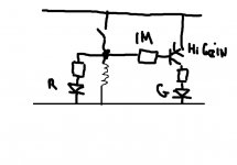
Is that an NPN device at the left ? Emitter to +18 volts ?
It doesn't quite seem to make sense as drawn. Is that white line a switch ?
LED current ? 150 ohm and 18 volt is far to high.
It doesn't quite seem to make sense as drawn. Is that white line a switch ?
LED current ? 150 ohm and 18 volt is far to high.
Excuse the awful drawing... I'm used to Paint in Vista and not W7
When the switch is closed the relay is closed and the red LED lights.
When the switch is open the red LED goes out, the relay opens and the green LED lights.
Don't forget a diode across the coil. The transistor should be high enough gain to saturate fully with a low base current (to prevent the red LED lighting due to base current from the transistor) although in practice the relay coil will swamp the effect and not allow enough volt drop to cause the red LED to light.
Attachments
Yeah, looking at it again that diagram isn't very helpful if you haven't been staring at it. I guess giving all the information when asking for help is part of the learning process.
Here's a new version of the schematic
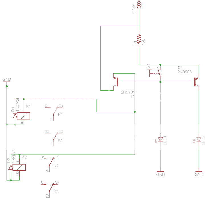
The transistor on the left is an NPN. The one on the right is PNP.
The LEDs are green radioshack deals rated for 12V (ie the have built in series resistors) The power supply is a wall-wart rated for 12v 350ma, but when I measure the voltage with my meter it says 18.6V so that's why I labeled it as +18 on the schematic.
I'm not sure exactly what the switch graphic is indicating, but it was the closest that I could find to what should be correct. It's a simple SPST paddle switch.
Here's a new version of the schematic
The transistor on the left is an NPN. The one on the right is PNP.
The LEDs are green radioshack deals rated for 12V (ie the have built in series resistors) The power supply is a wall-wart rated for 12v 350ma, but when I measure the voltage with my meter it says 18.6V so that's why I labeled it as +18 on the schematic.
I'm not sure exactly what the switch graphic is indicating, but it was the closest that I could find to what should be correct. It's a simple SPST paddle switch.
I haven't simulated it but it doesn't look right... so just thinking aloud looking at it and trying not to confuse T1 and Q1 🙂
With the switch open there is a conductive path via Q1 E-B junction. That will cause the LED1 to light and turn on T1 and the relay. That same current will also turn on Q1 and light LED 2. With the switch closed it's essentially the same except that LED 2 will go out. The relay will be energised in both switch positions.
With the switch open there is a conductive path via Q1 E-B junction. That will cause the LED1 to light and turn on T1 and the relay. That same current will also turn on Q1 and light LED 2. With the switch closed it's essentially the same except that LED 2 will go out. The relay will be energised in both switch positions.
- Status
- Not open for further replies.