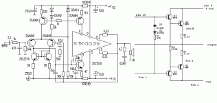
Here you find the datasheet of the STK0039 and the internal circuitry.
http://www.datadart.com/al/sanyo/Stk00.pdf
Hello! to Jamaica. I´ve been there 4 times.
http://www.datadart.com/al/sanyo/Stk00.pdf
Hello! to Jamaica. I´ve been there 4 times.
BillionPower said:Can someone look at this Mod and see if This can work and what other modifications needed.
Thanks
Hi Billlion Power!
Yes ...your modification will work!
You must take care of the thermal tracking of the output transistors and put a pot for adjusting the bias...i prefer to use a transistor as VBE for traking, but the diodes can work if you put them in thermal contact with the output transistors.
So ...turn on your soldering iron...
PS:Maybe the compensation need some fine tuning......
Yes!!! ..It's allways a good design pratice to put a capacitor across the biasing network!Duo said:Wouldn't it be even more effective to put the cap across the whol diode network?(right from base to base?)
I'm not perfetly sure on this one, but I've done and seen it before with good results. Any opinions?
Re: Circuit Modification success
The end of a perfect day...
BillionPower said:I did the modification and it worked like a charm. bias -/+ 0.56v.
The end of a perfect day...
- Status
- This old topic is closed. If you want to reopen this topic, contact a moderator using the "Report Post" button.
- Home
- Amplifiers
- Solid State
- Circuit Modification
