Post vacation brain train...
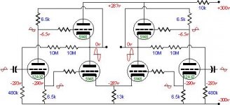
I'm looking at this circuit presented by John Broskie in TubeCad (Dec-99 article) and trying to figure out how to calculate for different tubes cause I'd like to try it...... Output is an alectrostatic headphone..
Circuit values seems odd, totem pole cathode resistor of 13k with 13v drop gives 1mA for 2 5965 tubes!!! (I can see there is a signal present but even soo...) Normally the current delivered by the tubes are sunk by the source (capacitor), I guess.
If top tube is close to cut-off as here, bottom tube conduct max, but I can't excatly calculate this because output (and reference) swings also.
Does anybody have an explanation of hoe to set operating point of top and bottom tube and how the resistors are calculated?
knubie
Attachments
Got a link to the article where that appears? From the look of it, it seems to be just part of a complete circuit. I'd like to see the original since Brosky often includes examples of what not to do, and this looks suspiciously like one of those
If it's intended to drive electrostatic headphones, then the low current isn't out of line, since electrostatics require high voltage, not high current.
If it's intended to drive electrostatic headphones, then the low current isn't out of line, since electrostatics require high voltage, not high current.
This looks like 0.65mA per tube in the diff amp, consistent with what's shown in the cathode circuit. It's low, but the voltage across the 5965s is quite high. The diff circuit's symmetry (it appears to be driven by a split-load inverter) and the feedback will reduce the distortion that the low idle current would normally cause.
edit: It appears that there's a slight error on the 12AX7's voltages.
edit: It appears that there's a slight error on the 12AX7's voltages.
Thanks fellow's...
Miles:
http://www.tubecad.com/december99/page6.html
But electrostatics need current too to charge the capacitance at high frequency....
Sy, yes looks like 0.65mA.
I was thinking of testing this with a 6CK4 tubes , but with more current... and maybe the 5965 as splitter tube instead...
So brain train continues...
For idle state with -300V over bottom tube 35mA gives approx a 900 Ohm cathode resistor which then drops about 31V, and we have approx. -269V over the bottom tube.
Top tube must then be set to draw 35mA at 269V also, so we will have to set -31V bias for top tube and set PS voltage at 269V, so far so good...
Is bias setup of a totem pole, this simple? Or is something missing???


Continuing... So top of split load phase splitter must be set to give -31V grid bias to the top tube. 31k at 1mA will do nicely, but then bottom of split load needs to give -31V as well with respect to bottom tube cathode, which is -269 + 31 = -300V
We have to use same resistor in top and bottom of a split load phase splitter so 31k will be used in the bottom but then we need -331V at the bottom of this resistor.
OK.
-31 +- 331 = 300V at 1mA sholud do nicely with 2,75V grid bias for the 12AX7 according to spec. (so we really need -334V PS)
I have to drop 31V in the negative rail since this is raised to -331V or recalculate output stage cathode resistor to 1.8K which sets cathode voltage to -269V again...
Same for positive PS, must drop from 334 to 269, a bit wasteful, any better ideas
I guess most of this will somehow self balance or find it's equilibrium, hopefully at some place below max dissipation limits
Does any of this seem remotely correct, comments PLEEEEASE...

Miles:
http://www.tubecad.com/december99/page6.html
But electrostatics need current too to charge the capacitance at high frequency....
Sy, yes looks like 0.65mA.
I was thinking of testing this with a 6CK4 tubes , but with more current... and maybe the 5965 as splitter tube instead...
So brain train continues...
For idle state with -300V over bottom tube 35mA gives approx a 900 Ohm cathode resistor which then drops about 31V, and we have approx. -269V over the bottom tube.
Top tube must then be set to draw 35mA at 269V also, so we will have to set -31V bias for top tube and set PS voltage at 269V, so far so good...
Is bias setup of a totem pole, this simple? Or is something missing???
Continuing... So top of split load phase splitter must be set to give -31V grid bias to the top tube. 31k at 1mA will do nicely, but then bottom of split load needs to give -31V as well with respect to bottom tube cathode, which is -269 + 31 = -300V
We have to use same resistor in top and bottom of a split load phase splitter so 31k will be used in the bottom but then we need -331V at the bottom of this resistor.
OK.
-31 +- 331 = 300V at 1mA sholud do nicely with 2,75V grid bias for the 12AX7 according to spec. (so we really need -334V PS)
I have to drop 31V in the negative rail since this is raised to -331V or recalculate output stage cathode resistor to 1.8K which sets cathode voltage to -269V again...
Same for positive PS, must drop from 334 to 269, a bit wasteful, any better ideas
I guess most of this will somehow self balance or find it's equilibrium, hopefully at some place below max dissipation limits
Does any of this seem remotely correct, comments PLEEEEASE...
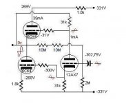
Well my calcs was probably much to caotic for anyone to follow...
Anyways I'll try again, a since a picture says more than a 1000 words...
Something like this....
The 12AX7 is a too wimpy tube to use in this position as a phase splitter but it's just for illustration purposes...
The driver tube (not shown) in front of the split-load phase splitter (12AX7) has to deliver 30-40V RMS with some power and low Z to drive a couple of 6CK4 to full tilt.
Maybe a 6SN7 would be better?
Attachments
- Status
- Not open for further replies.