Scheme circlotron is not going to. Preparations are under way. Drawn PCB output stage. Your card is already collected. Here is the schematic. Please feel free to contact if you have any questions.Hi, Do you have any specs or measured/SIM data to show?
THx-RNMarsh
Attachments
Scheme circlotron is not going to. Preparations are under way. Drawn PCB output stage. Your card is already collected. Here is the schematic. Please feel free to contact if you have any questions.
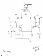
Hello FEDOSOFF. I hope that you are well. I am glad to see that you are expanding the use and value of your patent application. Please explain the symbols of the "diodes" in the circuit of the Circlotron. Also, pls clarify the connections at the loudspeaker; they cross on top of each other! Thanks
I need to study [carefully] your schematics above so as to appreciate and grasp their workings and value.
Best regards
Antoinel DIODES INDICATE THE POWER SUPPLY. Scheme circlotron has no singularities except system balance control current. The Converter current voltage showed good results. For example, if 10 volts output ( RMS ) harmonic distortion was 0,008%. Please feel free to contact if you have any questions.
Antoinel DIODES INDICATE THE POWER SUPPLY. Scheme circlotron has no singularities except system balance control current. The Converter current voltage showed good results. For example, if 10 volts output ( RMS ) harmonic distortion was 0,008%. Please feel free to contact if you have any questions.
Thanks FEDOSOFF.
Hello colleagues, I propose to discuss the scheme CIRCLOTRON ON FIELD-effect TRANSISTORS WITH a STABILIZATION SYSTEM MODES.
Hi Fedosoff,
There is a slight mistake on the schematic.
R20, R14, D3, D6 all have to be connected to the right side of R29, not the left one.
In overall - a cool circlotron source follower.
Cheers,
Valery
Well boys, any generic three stage amplifier, like Blameless for example
Can offer you the same or better performance without all that complication.
I suggest you boys, to check together your psycho analist the reasons why you choose to spent time and dedicate yourself into an overcomplicated design to achieve the same performance already obtained by hundreds of earlier and much older designs.... , more complicated and offering you worse performance considering specifications.
Overcomplicated design does mean an overcomplicated mind...and not someone that is wise... and because wisdom, can create such confusion..... straight line is still the smallest and closest distance between two points... despite we do not have straight line in the universe due to gravity..but we can simplify...or not?
I hope it is just an exercise, to have fun achieving same result with overcomplicated circuit....because if different than that, you may spend a lot of money and time to heal from that together a psycho analist layed into a couch.
Just to remind folks....now a days, forum amplifiers, a lot of them, are high efficient and THD is not more than 0.000150%
regards,
Carlos
Attachments

Last edited:
In the left part of the diagram was a small error. Now it is corrected.Hi Fedosoff,
There is a slight mistake on the schematic.
R20, R14, D3, D6 all have to be connected to the right side of R29, not the left one.
In overall - a cool circlotron source follower.
Cheers,
Valery
Attachments
Nonlinear distortion in such schemes and harmonic suppression depend on the accuracy of the balance of currents. Also, do not always 0,000 % will correspond to a good sound.Can offer you the same or better performance without all that complication.
I suggest you boys, to check together your psycho analist the reasons why you choose to spent time and dedicate yourself into an overcomplicated design to achieve the same performance already obtained by hundreds of earlier and much older designs.... , more complicated and offering you worse performance considering specifications.
Overcomplicated design does mean an overcomplicated mind...and not someone that is wise... and because wisdom, can create such confusion..... straight line is still the smallest and closest distance between two points... despite we do not have straight line in the universe due to gravity..but we can simplify...or not?
I hope it is just an exercise, to have fun achieving same result with overcomplicated circuit....because if different than that, you may spend a lot of money and time to heal from that together a psycho analist layed into a couch.
Just to remind folks....now a days, forum amplifiers, a lot of them, are high efficient and THD is not more than 0.000150%
regards,
Carlos
Hi Carlos,
This thread is not about THD. This thread is about the balanced current-coupled architecture. Some people don't understand / don't bother / too lazy / don't care exploring it. Fedosoff does care. And this is a very wise approach. Then it maybe blameless or whatever - doesn't matter. What matters - it's balanced and it's current-coupled with the source.
If you saw the video about Fedosoff's earlier development - class A amplifier with waterfall-kind-of cooling - well, you know, some DIY builds cost the same as a decent car. That one costs the same as a small apartment, from my perspective Plus you need to build a private power plant nearby
So what? That's his choice. I enjoyed watching, got a couple of ideas for myself - no problem
Let there be more designs - good ones, insane ones, expensive ones, cheap ones - different ones!
Cheers,
Valery
This thread is not about THD. This thread is about the balanced current-coupled architecture. Some people don't understand / don't bother / too lazy / don't care exploring it. Fedosoff does care. And this is a very wise approach. Then it maybe blameless or whatever - doesn't matter. What matters - it's balanced and it's current-coupled with the source.
If you saw the video about Fedosoff's earlier development - class A amplifier with waterfall-kind-of cooling - well, you know, some DIY builds cost the same as a decent car. That one costs the same as a small apartment, from my perspective
Plus you need to build a private power plant nearby So what? That's his choice. I enjoyed watching, got a couple of ideas for myself - no problem
Let there be more designs - good ones, insane ones, expensive ones, cheap ones - different ones!
Cheers,
Valery
Sorry, not quite following... I must be missing something and not understanding.
Where is the audio input/drive applied?
Why (there must be a good reason) do the same devices, left side and right side get different polarity bias voltages?
_-_-
The tracking system stabilization modes will allow you to apply the transistors of the " box ".
Sorry, not quite following... I must be missing something and not understanding.
Where is the audio input/drive applied?
Why (there must be a good reason) do the same devices, left side and right side get different polarity bias voltages?
_-_-
R29 - D6 and R 28-D11 cut the negative period of the voltage.
Attachments

Where is connected the feedback ?
The accuracy of the balanced currents depends on the resistors R13,R15 and R17,R19. They have to pick up.Feedback can be connected to another device.
Attachments
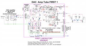
Hello FEDOSOFF. The image shows a schematic of your differential 'improved current source" with modifications so as to possibly convert it to a Class A power amp; right there, and not wait to do it several steps downrange.
1. I increased the current transfer ratio [to the power output bjts] by a factor of 100:1
2. I used a voltage step down output transformer to couple power output to a loudspeaker.
3. I assumed one can do a "digital volume control" inside the DAC before its L+ and L- outputs are released to the outside world
Is this a viable option?
Best regards.
3.
Attachments
- Status
- This old topic is closed. If you want to reopen this topic, contact a moderator using the "Report Post" button.
- Home
- Amplifiers
- Solid State
- Circlotron on field-effect transistors with a stabilization system modes.