Hi friends. This my very first post.
First off, I decided to name myself after what I think is the most fascinating amplifier topology I have ever seen - the circlotron. It is a model of simplicity and symmetry. I particularly like it because after drawing the basic circuit about 50 different ways to try and make it look the most logical, I noticed that if you place 2 loudspeaker loads on it, 1 between the sources and the other between the drains, it can be drawn as a perfect tetrahedron! As far as I was concerned that was the icing on the cake for a most aesthetically pleasing ampifier.
Now that I have firmly established my reputation as a nutcase, uh, sorry, *enthusiast*, Let me talk amplifiers. I discovered this circuit only a few months ago, and as it turns out I have quite a few large collection of hexfet switching type mosfets laying around at home. The last mosfet type amp I built was the Electronics Today one, back in about March '81 I think. It used complementary fets and I never felt comfortable with P-channel devices. They always seemed the poor cousin (or brother/sister?) to the N-channel. Then I found the circlotron cct that would let me use both N-channel devices. Coolarama! I wound up a driver transformer, picked a matched pair and away it went.
I started a thread on Google Groups that I will part copy and paste to here, telling of my adventures with this cct if anyone is interested. One unusual thing I did was to use a ferrite core tranny normally used in a switchmode supply for the driver tranny. With sufficient turns on the core it works really well, contrary to the advice I was given by others.
Anyway, I think the topology is the greatest thing since sliced bread. I hope there are others out there that are perceptive enough ;-) to also see what is so great about this cct.
Regards. GP.
The Circlotron Circle
Hello Aussie,
Do you have links for FET versions ?
This might even get Harry in a spin !.
Regards, Eric.
Hello Aussie,
Do you have links for FET versions ?
This might even get Harry in a spin !.
Regards, Eric.
GP, in case you are not aware, there is another thread related to this subject in which you may want to get involved:
http://www.diyaudio.com/forums/showthread.php?threadid=3802
http://www.diyaudio.com/forums/showthread.php?threadid=3802
Re: The Circlotron Circle
What do you mean FET version? Audio specific FETs or something else? Attached is the current version of the o/p schematic drawn for optimum clarity of seeing how it works. FETs are IRF540, rails 20v, resistors to earth = 100R, broken wire ends go to 3.5 volt bias supply, driver tranny is wound on ferrite 1:1:1 ratio as previously mentioned. Not that the circuit really needed posting or anything, I just love it that's all.
Who is Harry that he might get in a spin?
GP.
mrfeedback said:Hello Aussie,
Do you have links for FET versions ?
This might even get Harry in a spin !.
Regards, Eric.
What do you mean FET version? Audio specific FETs or something else? Attached is the current version of the o/p schematic drawn for optimum clarity of seeing how it works. FETs are IRF540, rails 20v, resistors to earth = 100R, broken wire ends go to 3.5 volt bias supply, driver tranny is wound on ferrite 1:1:1 ratio as previously mentioned. Not that the circuit really needed posting or anything, I just love it that's all.
Who is Harry that he might get in a spin?
GP.
Attachments
Harry Who ?
Hi mate,
Quick Google search gave mainly tube circuits.
Maybe yous is the afterburner circuit that I have been looking for.
I agree that tranny coupled driver stage ought to be sonically decent.
Harry seems to have a thing about FETS - and I'm happy to listen to his advice - go search H.H and you are sure to find plenty of good advice, and unfortunately much flak also - ignore this stuff, for his experience and advice is GOOD.
Regards, Eric.
Hi mate,
Quick Google search gave mainly tube circuits.
Maybe yous is the afterburner circuit that I have been looking for.
I agree that tranny coupled driver stage ought to be sonically decent.
Who is Harry that he might get in a spin?
Harry seems to have a thing about FETS - and I'm happy to listen to his advice - go search H.H and you are sure to find plenty of good advice, and unfortunately much flak also - ignore this stuff, for his experience and advice is GOOD.
Regards, Eric.
re: de palma
Did he get his labeling of the battery polarity wrong, or
are his fets labeled with the arrow in the wrong direction?
Yv
Did he get his labeling of the battery polarity wrong, or
are his fets labeled with the arrow in the wrong direction?
Yv
I'd say they are meant to be pnp bipolars. It did mention them in the text as being such, at least for one version of the circuit.
Well it's a Circlotron all right. I remember seeing that one about a year ago and it did not occur to me that there was something special about that topology.
Did you get a load of that cct number three?? I'll bet he never actually made it. What makes me say that is the diodes in the source legs of the driver fets. He says they are for temp compensation but higher temp means lower diode drop so the source is pulled lower (equals gate being pulled higher) and so both the drivers are turned on harder, the output fet gates are pulled further apart, quiescient current rises, and whoa! you got thermal runaway. 😱
Bruce DePalma's N-machine was always surrounded with controversy. I have my doubts about this thirs amplifier cct too.
GP.
Hi everybody. This is how the project is progressing. As you can see I have made the output into a Sziklai pair on the suggestion of AKSA, (thanks heaps, mate🙂 ). This makes the output LOTS more linear. As an example, before I had to use ~200mA quiescent current to eliminate crossover distortion, now I can do it with 75mA. Actually I am running 100mA right now and may return to 200 and see if it sounds and better.
The fets are now tricked into thinking they are P-channel devices and so the whole circuit is upside down. It looks a bit confusing at first, but take my word for it, the things works. To me it sounds just so smooth and clean. Even through that 3C90-cored input tranny!
Next thing to do is figure out some feedback from output to input because the output impedance is 0.47 ohms courtesy of the "source" resistors (that are connected to the drains).
I have not cranked the volume way up yet because of lack of drive voltage avaliable. I gotta make a preamp for it yet. Doesn't that symmetry of the schematic make your mouth water?😉
GP.
Attachments
Hello Circlotron
More seriously, this setup looks pretty ideal in terms of total symmetry.
Have you tried a step up transformer as the driver transformer to increase input sensitivity ?
Are you finding the 0.47 ohms output impedence to be a problem ?.
This has to be pretty much minimum component count output stage, and well suited to tri-amp cabinets ?.
Do you have any distortion/performance figures ?.
Please keep us posted on your results.
Regards, Eric.
Yep, nearly as much as the Cantonese Chicken I'm enjoying right now !.Doesn't that symmetry of the schematic make your mouth water?
More seriously, this setup looks pretty ideal in terms of total symmetry.
Have you tried a step up transformer as the driver transformer to increase input sensitivity ?
Are you finding the 0.47 ohms output impedence to be a problem ?.
This has to be pretty much minimum component count output stage, and well suited to tri-amp cabinets ?.
Do you have any distortion/performance figures ?.
Please keep us posted on your results.
Regards, Eric.
Yes, symmetrical it is alright. If you have a matched pair of drivers you don't even need to match the output fets! They get forced to be the same as the drivers. That means you could go and buy just 2 output fets and a handfull of MUCH cheaper drivers and sort through *them* to find a match, rather than have to match the big guns. Cool huh? 🙂
Also, when doing bias temperature compensation you are normally concerned about output device junction temperature, but the trouble is if you are dumping say 50 watts heat per device, the junction could easily be 25 deg C higher than the tab, which is of course at a higher temp than the heatsink. It's difficult to get an accurate picture, but with the Sziklai pair here, we are only interested in the temp and the Vbe of the drivers. Provided the output fets are not melting, their temp doesn't matter at all. That is why I used TO-220 type driver and temp sensor, so they could all be bolted together thermally separate from the output fets. It is only the temp of those first three that matter, and seeing the drivers don't dissipate very much, their tab temp is very close to their juction temp! Yay! That notwithstanding, for the bench proto I have everything on the one heatsink. I'll have to post a pic. Right now with the present cct the standing current goes from 200mA @ 20 deg C to 223 mA @ ~60 deg C. I may fiddle with this bit further and have something that automatically reduces the bias after a few minutes of no program material.
The 0.47 ohm output impedance seems mostly to be a problem when I think about it. 🙂 I would like to eliminate it though. Just gotta find out a nice way to add feedback. Maybe a gigantic low voltage cap across each source resistor would do the trick. I looked at using a 1 Farad 5v memory backup cap but they have an internal resistance of several tens of ohms. No good.
The driver tranny ratio at the moment is effectively 1:4 stepup and yes, I do want to increase this. The reason I "chose" this ratio is because I used sixfilar twisted wire with 1//1 as the primary and (1+1)ct(1+1) as the secondary. Not a lot of choice here! The twisted wire gives *rock solid* coupling which I would not get with an unequal amount of primary/secondary turns because the wires would have to be separated. Nevertheless, I will give it a go because it may just be good enough.
I did say in the last post that I was using 100 mA bias, well I cranked it up to 200 mA. It doesn't seem to sound any different but one thing is certain: whereas before at a sound level where you could have a conversation without really raising your voice, the dc supply current was jiggling up and down with the sound, now it stays completely stable until the volume is turned up a little louder still. This means (I think) that it is running in class A to quite a reasonable listening level, as per the steady current drain. Now the feedback of the transistor pair is not working so hard either so I would think that is a good idea. Well that's about it for now. Thanks for the encouragement Eric.
Mmmm... symmetry...
GP.
Last edited by a moderator:
Regarding the psu bypass caps
It seems to me that these have to be really good quality
ones since it is important to have as low an impedance
as possible from the drain of the output fets to the 0R47
resistors. Is this requirement even more important
in a circlotron compared to say the standard PP amp?
One question that has puzzled me regarding the
Sziklai - how does one choose the value of the collector
resistor for the bjt? In the attached ckt, it is 100 ohms.
What are the requirements and trade-offs to make?
I can see the following:
i. make it large -> more signal fedback -> better linearity
does the thermal stability and ac stability suffer?
ii. make is smaller - opposite as above?
In a true emitter follower, this resistance is zero; in
the Sziklai, this is significantly larger so in what way is
the bjt a follower?
thanks in advance,
Yv
As far as power supply rail caps in amplifiers are concerned, think of it like a linear power supply. You have the series pass element as an emitter follower which is the same as the output device in an amp. Any variation in the voltage upstream of the power device i.e. on the collector because of ripple, voltage sag under load, wobbly caps etc won't appear on the emitter side, at least it is reduced by the same factor as the open loop voltage gain of the circuit. If you have infinite gain and speed then *no* bad stuff gets through to the load. The yuckiest caps will do. Less than infinite gain and speed need bigger and better caps. What goes into commercially made amplifiers depends on what will satisfy the user. Since us diy'ers are the most discerning of all users we use the biggest caps we can afford, even if others can't hear the difference.
I would not think the circlotron is any more critical about caps than other topologies. It is after all just a pair of emitter followers.
The 100 ohm resistor would not have the effect you predict because it is in the collector cct of the driver. If it was in the emmiter cct therefore in series with the drive and output signals then yes it would possibly have some effect. I haven't tried it yet but I think I will. Thanks for that.
I chose the 100 ohms so the fet gate would have roughly the same pull up and pull down resistance - 1000 ohms vs 1100 ohms. To high a resistance in the gate cct makes the fet turn off slow. I was going to use a 470 ohm but I saw a 1k first! Also for 100 ohms, too low a value reduces the bjt gain so it doesn't linearise the whole show as well as it would, and also makes the driver get hot.
The bjt works as a follower because when the base rises, the collector only pulls the gate away from the source about 4 volts and then the drain (acting like a P-channel source) starts to move, taking along with it the bjt emitter. Then the bjt is happy because it wants to keep it's emitter always one Vbe below it's base. If need be it tells the fet to move heaven and earth so it's Vbe remains steady. Full of it's own importance it is, this little mouse making the elephant do it's bidding.
GP.
Pesky output impedance
The next problem has me sorely vexed.😕 The source resistors have to be inplace because otherwise the transconductance of the output devices would be so high that as you adjust the bias up from zero you would get to the point where the output devices begin to conduct and *WHAM* they are on full 😱 and there is no latitude for adjustment. It's max or nothing. The source resistors allow the thing to gradually slide into conduction and help it stay at the set point. Trouble is, they are effectivley in series with the loudspeaker and this is undesireable.
I have this feedback cct in mind (normal source follower drawn) that takes the varying voltage drop from across that doggone** rersistor and adds the AC portion of it to the signal voltage so the source now swings one resistor drop higher than what it would have done, and the bottom end of the resistor that goes to the load swings the full distance.
The only problem I can foresee (haven't built it yet) is that because the error voltage is assymetrical because it is from only one half of the waveform the lower cap will do a dc shift on the voltage and make something go funny somewhere. We'll see.
GP.
Attachments
Hi guy, we have built a prototype of a cyclotron circuit using two BUZ and now it works and deliver 3 watts with a double 12V power supply.
The input stage is a all FET circuit.
This is only the first step of a complete project of a DIY ciclotron amplifier that we are developing for the Audiofanatics.
All the project is up to come on www.audiofanatic.it
ciao
Filippo
www.audiofanatic.it
The input stage is a all FET circuit.
This is only the first step of a complete project of a DIY ciclotron amplifier that we are developing for the Audiofanatics.
All the project is up to come on www.audiofanatic.it
ciao
Filippo
www.audiofanatic.it
Sorry, I can't find the amplifier you mention. All the pages are inSpanish and I could only gues about every fourth word. 🙂 Could you give an exact link to it? Or when you say "All the project is up to come" do you mean that it is still coming, not here yet?
GP.
GP.
One thing about living in this part of the world is that as I write it's 5:30 Friday afternoon for me. 🙂 Most of you have to wait maybe 17 to 20 hours yet. Time to go home from work and play amplifiers for the weekend. Yay! Maybe you should all think about emigrating to Australia's east coast. DIY electronics is alive and well here.
Anyway.... here is the latest incarnation of the Circlotron Doomsday Amplifier, CDA if you like, and after thinking about various ways of applying feedback to lower the output resistance therefore ensuring the amp has a tighter grip on speaker cone movement ("when ah sez whoa speaker ah means whoa!" (with apologies to Yosemite Sam and that camel)) I bit the bullet and returned to the idea of using opamps. My last try at that gave new meaning to the word MegaFlop.
I have initially limited the gain of the opamps to x3.2 courtesy of the (22k + 10k divided by 10k) resistors instead of letting them go flat out because the amp would almost certainly oscillate and squeal it's head off. I'll gradually increase the value of the 22k's bit by bit and see how it goes. If it will stand x10 gain from the opamp the entire cct will still have a gain of one from input to output but the output impedance will be reduced by a factor of 10. I write it like this for the benefit of newbies because I was there once too and it took years and years to figure out what all that stuff did. I used to think a hex inverter inverted hexes, whatever they were! True!
It's nearly a quarter to six! Time to go home for dinner and then out to the shed for more experiments. Hooroo!
GP.
Attachments
Sorry, the project isn't on line because we must solve some problem due to the high input capacitance of the BUZ. Stay cool
ciao
Filippo
www.audiofanatic.it
PS the language is not Spanish but Italian
ciao
Filippo
www.audiofanatic.it
PS the language is not Spanish but Italian
I spent a lot of the weekend doing mechanical details of the CDA and will try and attach a few pics if my internet connection doesn't time out on me. Also I have been fiddling with various temperature compensation schemes. The last on I used had four schottky's in series to get enough mV per degree. I assume that they have the same tc as a normal diode? Anyway, 3 undercompensated and 4 overcompensated. 🙄
Then I got to thinking that seeing I only have to be concerned with the temp and consequently the Vbe of the drivers, why not put them on their own slab of metal and heat it to say 60 deg C and maintain it at that with another transistor and temp sensor bolted to it. If there is constant temp then you just set the bias and forget it! Provided the metal is abve the temp that the 3 watts total of driver dissipation would raise it to then you can maintain that temp constant! That will have to be my next experiment. Whoops! ISP timing out in 2 minutes, no time to post pics.
GP.
CDA is not vapourware.
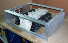
OK here's a coupla pics to show it isn't just vapourware 🙂 Caps are all 4700uF 50v but running at about 40v at this point. Total of 66 with 2 spare so that's two lots of 75,200 uF per channel. They were free and they were doing nothing, so I used them.
The transformers are a bit of a mixed bag. They were brand new and free, just with slightly damaged terminals. Each one is 360va and has 12v 3A, 28v 4.2A, 29v 7A. I will use the 3 29v 7A windings and parallel 2x28 volt windings for 8.4 amps for the 4 rails . A slight mismatch but this will have to do until I get some nice toroids.
The Hexfets are now STY34NB50's, a Super TO-247 package with no hole and whopping big dies. I wasn't going to use them originally but the dissipation rating of 450 watts was just too hard to resist. They are mounted directly to the 2 inch square by 3/16" copper slab using Thermstrate compound, and between the copper and the aluminium is a sheet of Bergquist K-10. It has a Rth of 0.2 deg per watt per sq inch and I have 4 sq inches exactly so it would be about 0.05. I thought it was a better idea to do it this way rather than put the insulator straight under the fets and make a bottleneck for the heat flow given the much smaller surface area available.
Not quite as fancy looking perhaps as some of the *great* works of art and engineering and craftmanship that you blokes have posted, but I'm happy that I'm finally doing, and not just talking. This one is not a sports car - it's a truck.
GP.
Attachments
- Home
- Amplifiers
- Solid State
- Circlotron amp using N-channel mosfets