You need to post a schematic of your two cases for clarity. A picture is worth a thousand words, you know.
Here is an excerpt from National's application note AN-1490 (LM4702 Power Amplifier).
Quote:
"In listening tests at National’s sound room evaluating different
circuit components used in the LM4702 demo amplifier,
there was one part whose negative effect on audible signal
quality was undeniable. A DC blocking capacitor on the input
of the LM4702 degraded sound quality. In multiple listening
tests, with different participants and at various locations
around the country, the negative effects of even the best film
and foil polystyrene DC blocking input capacitors in the
audio signal path was confirmed. It is therefore recommended
that DC blocking capacitors not be used in the
signal path for mid to high-end audio equipment. Where DC
offset from another signal source may be a problem then the
use of a DC servo circuit that keeps DC offset from appearing
at the output of the amplifier is recommended."
DC protection comes at a price. Either at the price of sound quality with AC coupling or at the price of a more complex and expensive design with DC servo and/or DC protection circuits at the output or an audio transformer at the input, etc.
AndrewT said:I think Daniel is trying to tell us that his amplifiers become oscillators when he adds/removes capacitors anywhere between the transformer primary and the speaker terminals.
Not squarely on topic.
Yes, there's misbehavior if a cap is connected series to either input.
Except that "Case 1" doesn't misbehave.
Except that "Case 2" might help a poorer cap.
AndrewT said:His question should be
"how can I ensure my chipamps are not oscillating"?
This is welcome. Improving that tolerance is beneficial.
The two comments taken together lead me to assume that we could dodge the audio effects of "cap at CI" via tuning all other parts to compensate. Yes, of course, but I wouldn't be able to explain how to do that. This wouldn't be safe for the project.
BWRX said:You need to post a schematic of your two cases for clarity. A picture is worth a thousand words, you know.
Oh yes!
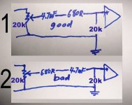
Comparing the + input with the - input. . .
Case#2 makes the same distortion as "cap at CI."
Attachments
pacificblue said:. . .DC protection comes at a price. Either at the price of sound quality with AC coupling or at the price of a more complex and expensive design with DC servo and/or DC protection circuits at the output or an audio transformer at the input, etc.
Thank you!
Yes, AC coupling won't have as much resolution, but it does have finer dynamics, and I'm hoping for "an even trade" there.
The main problem is frequency response.
Re: Re: CI, is that RC backwards?
Yes. But the drawing supports the theory...analog_sa said:It made more sense without a circuit.
...which is true for case #1 as long as the potentiometer is not set to full volume. Surprise, surprise! That is the case labeled as good. The question about where to place Ci should thus be answered.Mooly said:The cap is more prone to pick up noise due to it's physical size and so should be at the "low impedance" end as a generalisation.
Re: Re: Re: CI, is that RC backwards?
Results are near-identical if the potentiometer is omitted.
pacificblue said:Yes. But the drawing supports the theory...
...which is true for case #1 as long as the potentiometer is not set to full volume. Surprise, surprise! That is the case labeled as good. The question about where to place Ci should thus be answered.
Results are near-identical if the potentiometer is omitted.
thanks for the pictures.
However, the capacitors shouldn't pick up very much LF or RF noise.
Me guesses there is a more general layout/wiring issue, that makes your amps sensible to RF and oscillations.
regards
However, the capacitors shouldn't pick up very much LF or RF noise.
Me guesses there is a more general layout/wiring issue, that makes your amps sensible to RF and oscillations.
regards
you are about the 20th person to suggest that Daniel's circuits are susceptible to the onset of instability.Juergen Knoop said:the capacitors shouldn't pick up very much LF or RF noise.
Me guesses there is a more general layout/wiring issue, that makes your amps sensible to RF and oscillations.
If that is truly the case then it explains why he finds capacitor changes are having such a profound effect on sound and on operating temperatures.
It is this combined effect that convinces me he has oscillation problems.
AndrewT said:you are about the 20th person to suggest that Daniel's circuits are susceptible to the onset of instability.
If that is truly the case then it explains why he finds capacitor changes are having such a profound effect on sound and on operating temperatures.
It is this combined effect that convinces me he has oscillation problems.
Given that this is altogether too likely with a chipamp, I wouldn't dispute it; however, the several kits that I have tried performed worse than my own perfboard creations.
My question is how to do AC coupled NFB without so much harm to frequency response. Example: The amplifier works well for its job with ONLY a resistor; but, if the cap is added (series, of course), then the amplifier's frequency response becomes unlevel with just that one change.
The circuits quoted are common, and not specific to me.
some things have to repeated quite often, until the knowledge settles. 😀you are about the 20th person
Of course I'm sitting on a comfy chair in front of my computer screen and have no slightest idea, how Daniels amplifiers perform technically or how significant the perceived changes in sound quality are.
you are not blamed in person.The circuits quoted are common, and not specific to me.
A lot of people get confused by exemplary circuits published in data sheets.
regards
Juergen Knoop said:
some things have to repeated quite often, until the knowledge settles. 😀
Of course I'm sitting on a comfy chair in front of my computer screen and have no slightest idea, how Daniels amplifiers perform technically or how significant the perceived changes in sound quality are.
you are not blamed in person.
A lot of people get confused by exemplary circuits published in data sheets.
regards
Well, if that's the general consensus, then the issue won't be solved without a scope.
However I'd like to believe that the fine people who produce kits, and the people who publish board layouts, would have discovered a solution long ago. Saying that its up to me is very funny!! Its not the humorous sort of funny.
a scope is a basic tool for someone designing amplifiers.
Don't using it, seems a funny thing for me. 😉
And yes people have thought about stability issues a long time ago, before the Gainclomania had begun.
I own such industrial made boards, which allow full featured LM3886 circuits.
Now the market is flooded with different things. 😱
You have a rich fantasy regarding electronics and amplifiers.
Asking you to verify basic functionality and reliability of your circuits, is probable asking to much.
But sometimes you may want to leave the Mystery Forest and then things have to be checked before making claims. 🙂
regards
BWRX said:You need to post a schematic of your two cases for clarity. A picture is worth a thousand words, you know.
Hey bud! The farther this went, the more convinced I am that your balanced input designs (with onboard buffer) are absolutely brilliant.
I believe that I'd need 3 conductors (per each channel) running all the way. . ., only joining down to 2 conductors "at the last minute," for RCA jacks on the rear panel of the amp. Doesn't that result in "input star ground" at the RCA jacks?
Juergen Knoop said:But sometimes you may want to leave the Mystery Forest and then things have to be checked before making claims. 🙂
Two things:
1). It has become apparent that I need some additional schooling and tools in order to progress. This is not available within commuting range. Impasse! Any ideas?
2). Given a rather huge forrest and some outdoor speakers, its great fun to cause heat to some TDA7294 (in the correct way to do so). 😀
It seems that studying design tools (#1), at this time, is more important than studying realistic concert presentation (#2), yet if you were forced to pick only one, which would it be?
danielwritesbac said:My question is how to do AC coupled NFB without so much harm to frequency response.
Use a good quality cap of a large enough value so that the corner frequency of the filter produced by adding the cap is below the audible frequency of interest. National tells you how to do this in the datasheet for the part.
In theory, using ideal parts, the 2 scenarios you sketched are identical. In the real world the parts are not ideal and have parasitics BUT they should not have any audible impact in a decently built amplifier. The difference you are hearing could very well be due to the placebo effect. Just use what you think sounds best.
danielwritesbac said:The farther this went, the more convinced I am that your balanced input designs (with onboard buffer) are absolutely brilliant.
I do believe that balanced input designs are worth pursuing. The circuits I built are just high power versions of an instrumentation amp geared towards audio use. I did not come up with the instrumentation topology - it has been around for a long time.
danielwritesbac said:I believe that I'd need 3 conductors (per each channel) running all the way. . ., only joining down to 2 conductors "at the last minute," for RCA jacks on the rear panel of the amp. Doesn't that result in "input star ground" at the RCA jacks?
Most balanced connections use 3 wires: +,-, and ground. Even though the source and amp share a ground the amp only cares about the difference between the + and - balanced signals. This way ground loop currents have a negligible effect on the signal.
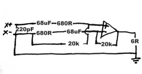
BWRX said:. . . .This way ground loop currents have a negligible effect on the signal.
Is this anywhere close?
Attachments
aah, don't ask me and don't force yourself.danielwritesbac said:
yet if you were forced to pick only one, which would it be?
Once you have gone deeper in electronics, you may feel the need or wanth for an oscilloscope. Buy it then, or buy it now, if you see a bargain.
Let the things their natural flow.
It's a hobby you know and you are getting crazy about it soon enough. 😀
regards
danielwritesbac said:
Is this anywhere close?
Hi Dan,
Have you considered getting one of the free schematic design programs? It would make your illustrations a bit clearer.
Attachments
- Status
- Not open for further replies.
- Home
- Amplifiers
- Chip Amps
- CI, is that RC backwards?