It's taken three years 🙁 and way too much thinking, rethinking, and overthinking, but the wire stretching idea I posted in 2006 has finally come to life. Way back when I posted a sketch of an idea:
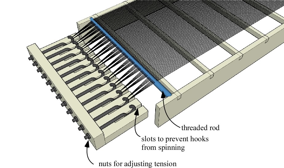
I then proceeded to come up with several "improved" ideas as I finally got around to putting some wire stators together. Let's just say I learned several lessons at the school of hard knocks and ended up returning to a variation of the original plan. Here's what I'm in the midst of using to stretch 24 gauge, heavy build, magnet wire. The wires have a center to center spacing of 1 mm which yields about a 45% open area.
I got frustrated using threaded rod as a wire spacer so I made a mold out of delrin and aluminum so that I could create some "combs" that hold the wire in place more securely. The combs are molded out of two part polyurethane. It's neat stuff, and takes about 15 or 20 minutes to harden up enough so that I can remove it from the mold and start another comb. I used the combs to space the wires near the threaded hooks (you can see a horizontal row of three of them in the first photo, just above the hooks) and also made a bunch more to keep the wire spacing consistent along the length of the stators. The following photo shows the aluminum and delrin mold, and three cream colored wire spacers that I made with it.
I've just made my first attempt at using this system, and have to admit that my technique still requires refinement. I managed to cause a few wires to be misaligned as I glued them to the cross members using hot melt glue. The photo below makes the imperfections plenty obvious, but I'll swallow my pride and post it anyway. I'm hoping that I can do a neater job on the next stator. I definitely learned from a few mistakes in the process of putting this one together.
I'm not sure I've made clear how this scheme works, but I'll post this preliminary description and set of photos and others can let me know if I've created any confusion.
Few
I then proceeded to come up with several "improved" ideas as I finally got around to putting some wire stators together. Let's just say I learned several lessons at the school of hard knocks and ended up returning to a variation of the original plan. Here's what I'm in the midst of using to stretch 24 gauge, heavy build, magnet wire. The wires have a center to center spacing of 1 mm which yields about a 45% open area.
An externally hosted image should be here but it was not working when we last tested it.
I got frustrated using threaded rod as a wire spacer so I made a mold out of delrin and aluminum so that I could create some "combs" that hold the wire in place more securely. The combs are molded out of two part polyurethane. It's neat stuff, and takes about 15 or 20 minutes to harden up enough so that I can remove it from the mold and start another comb. I used the combs to space the wires near the threaded hooks (you can see a horizontal row of three of them in the first photo, just above the hooks) and also made a bunch more to keep the wire spacing consistent along the length of the stators. The following photo shows the aluminum and delrin mold, and three cream colored wire spacers that I made with it.
An externally hosted image should be here but it was not working when we last tested it.
I've just made my first attempt at using this system, and have to admit that my technique still requires refinement. I managed to cause a few wires to be misaligned as I glued them to the cross members using hot melt glue. The photo below makes the imperfections plenty obvious, but I'll swallow my pride and post it anyway. I'm hoping that I can do a neater job on the next stator. I definitely learned from a few mistakes in the process of putting this one together.
An externally hosted image should be here but it was not working when we last tested it.
I'm not sure I've made clear how this scheme works, but I'll post this preliminary description and set of photos and others can let me know if I've created any confusion.
Few
Hi Few,
Your wire stretcher idea is very good. I'm looking forward to seeing your finished speakers. Thanks for sharing.
Wachara C.
Your wire stretcher idea is very good. I'm looking forward to seeing your finished speakers. Thanks for sharing.
Wachara C.
Thanks, Wachara C. I hope to have some satisfying progress to report.
In a previous variation on this stretcher I wrapped wire around a threaded rod with 2 mm pitch, and then over a threaded rod with 1 mm pitch in order to force all the wires into the same plane. I found that the fine threads in the 1 mm rod allowed the wires to pop out of position quite easily and I spent too much time trying to realign everything. With the scheme I'm using now I think there would also be problems because the wire approaches the "comb" spacers from a variety of angles (the wires from each 10 mm section of the stator all go around one hook or peg). The lateral forces from this arrangement would encourage the wires to hop out of their correct position on the threaded rod.
If I were to do it all over it might be possible to use the threaded rod, but I found having lots of extra polyurethane spacers has been very helpful in maintaining the spacing of the wires along the stator. Of course, my photos show I still need to do better job with that.
Finally, I enjoyed the mini-project of figuring out how to mold something with fine features with a material I hadn't worked with before. I started out making the spacers out of epoxy but the polyurethane is much much better for this purpose.
Few
why: "I got frustrated using threaded rod as a wire spacer"??
In a previous variation on this stretcher I wrapped wire around a threaded rod with 2 mm pitch, and then over a threaded rod with 1 mm pitch in order to force all the wires into the same plane. I found that the fine threads in the 1 mm rod allowed the wires to pop out of position quite easily and I spent too much time trying to realign everything. With the scheme I'm using now I think there would also be problems because the wire approaches the "comb" spacers from a variety of angles (the wires from each 10 mm section of the stator all go around one hook or peg). The lateral forces from this arrangement would encourage the wires to hop out of their correct position on the threaded rod.
If I were to do it all over it might be possible to use the threaded rod, but I found having lots of extra polyurethane spacers has been very helpful in maintaining the spacing of the wires along the stator. Of course, my photos show I still need to do better job with that.
Finally, I enjoyed the mini-project of figuring out how to mold something with fine features with a material I hadn't worked with before. I started out making the spacers out of epoxy but the polyurethane is much much better for this purpose.
Few
Thanks, Paul. I'm still a bit blinded by the images of perfection I had dancing in my head during the planning stages so the flaws look pretty prominent to me. I'm going to take a day off work tomorrow and try to put another stator together. We'll see if I learned anything while doing the first one.
Few
Few
"I'm still a bit blinded by the images of perfection I had dancing in my head"
I learned that the quicker you let those go. the sooner you get to enjoy your creation😀
I just improved my ribbons again yesterday, the ribbon suspension is becoming quite good...
Its constant and the work continues but for me it has been well-worth it given reward!
Looks like you are on the right path, glad to see people still sharing their kraft!
paul
I learned that the quicker you let those go. the sooner you get to enjoy your creation
Good advice. I'll try to follow it.
My hot melt glue approach does a surprisingly good job of grabbing the nylon insulation on the magnet wire, but it sure complicates the gluing process. I'm tempted to try epoxy instead, but my early experiments showed that it really doesn't adhere to the insulation as well. Maybe epoxy with some microspheres as filler would behave better. I don't relish the thought of changing my approach midstream, or having to rip apart the stator I've already made in order to switch adhesives. Hmmm.... more to ponder.
Few
I tried a quick test of polyurethane with and without thickeners to see if it would hold the magnet wire to the phenolic crossbraces. It might have worked, but it wasn't as strong a bond as the hot melt glue, and I like the fact that the hot melt glue's somewhat soft character when cooled also may do a nice job of damping any high frequency resonances in the wires. So, I ventured forth with the original approach--but with the advantage of a little practice--and put a second stator together. It went much faster this time, and while it's still not perfect, I think it's a significant improvement. By the time I'm done I'll really know how I should have done it in the first place.🙁 That seems to be the fate of the diy-er unless you're lucky enough to have the time to go through a thorough prototyping process. Or maybe I'm the only who suffers from this? Anyway, one more small step for man...
Few
Few
Few said:
Good advice. I'll try to follow it.
My hot melt glue approach does a surprisingly good job of grabbing the nylon insulation on the magnet wire, but it sure complicates the gluing process. I'm tempted to try epoxy instead, but my early experiments showed that it really doesn't adhere to the insulation as well. Maybe epoxy with some microspheres as filler would behave better. I don't relish the thought of changing my approach midstream, or having to rip apart the stator I've already made in order to switch adhesives. Hmmm.... more to ponder.
Few
Yesterday during lunch I noticed that Lowes now carries a 20 minute epoxy made for plastics.
It specifically lists nylon & PVC which are some of the tougher plastics to bond.
http://www.loctiteproducts.com/products/detail.asp?catid=17&subid=40&plid=866
http://www.lowes.com/lowes/lkn?action=productDetail&productId=44649-133-1151984&lpage=none
Interesting. Many thanks. I think I'm committed to continuing with the hot melt since I have two out of four stators done, but if--god forbid--I have to redo things, this looks very promising.
Few
Few
Recently, when I built a pair of Esl with stators made of green pvc coated garden wire, I tried several glues to fasten the wires to the alu frame, and the best was a cyanoacrylate called FXBond from MasterBond.
Hi Jonas,
very interesting and very purse-friendly your attempt using this garden wire,
but what about the isolation from shock hazard, did you check that?
Reg.
Frank
very interesting and very purse-friendly your attempt using this garden wire,
but what about the isolation from shock hazard, did you check that?
Reg.
Frank
- Status
- Not open for further replies.
- Home
- Loudspeakers
- Planars & Exotics
- Christening a new ESL wire stretcher