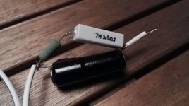
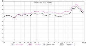
I found a few inductors (salvaged from other speakers) and tried with some resistors and this combination was the one that gave the nicest response:
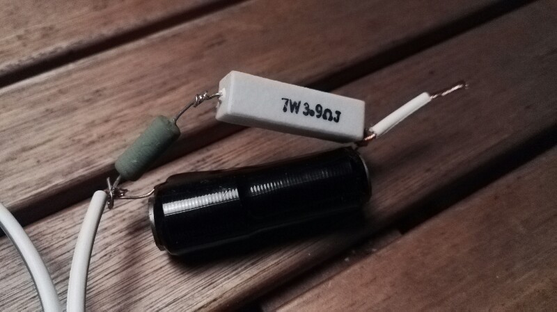
It's (3.9+1.8 Ohm) 4.7 Ohm and an unknown inductor (seems like an 1 mH unit).
This is the response:
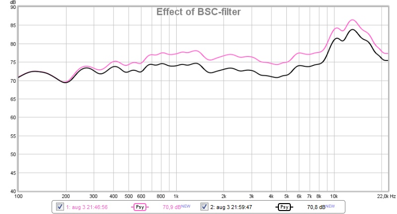
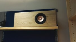
Now I'm trying them in my office, sound full and nice. Looks decent too:

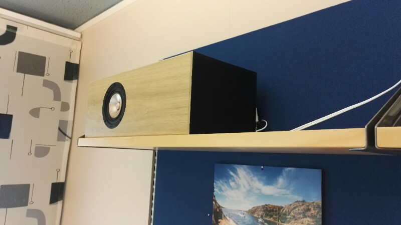
I'll build a box for the amplifier with the BSC, a power switch and a volume control (right now 1 % windows volume is loud enough).
/Anton
It's (3.9+1.8 Ohm) 4.7 Ohm and an unknown inductor (seems like an 1 mH unit).
This is the response:
Now I'm trying them in my office, sound full and nice. Looks decent too:
I'll build a box for the amplifier with the BSC, a power switch and a volume control (right now 1 % windows volume is loud enough).
/Anton
Attachments

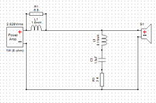
The rising impedance of the driver causes the top octave to be a little too bright. So I've ordered parts for making a notch filter and at the same time a slightly larger inductor for the BSC. Here is XSim result:
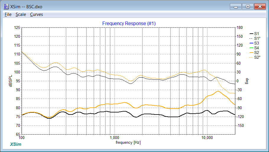
Filter construction:

Cost: About 15 € (I have capacitors already).
/Anton
Filter construction:
Cost: About 15 € (I have capacitors already).
/Anton
Attachments
Nice work Onni!
1mH and 5R is the usual 1st trial I use on a full range speaker like this for BSC. Sometimes just adding more R, like 10R can reduce that peak too rather than a notch. However, your notch sim looks great.
1mH and 5R is the usual 1st trial I use on a full range speaker like this for BSC. Sometimes just adding more R, like 10R can reduce that peak too rather than a notch. However, your notch sim looks great.
Thanks X!Nice work Onni!
1mH and 5R is the usual 1st trial I use on a full range speaker like this for BSC. Sometimes just adding more R, like 10R can reduce that peak too rather than a notch. However, your notch sim looks great.
I tried that as a first guess as well, but maybe the chr-70 requires slightly different values? I'm quite new to designing filters, I've mostly done DSP and PLLXO:s so far.
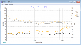
My last post was with a ZMA-file for the RS100-8 (they looked very similar). Now I've learned to trace the figure, so the curves look slightly different.
Here's a comparison of:
Black: No filter
Red: My proposed filter (1.6 mH+6.8 Ohm BSC + notch at ~13 kHz)
Blue: BSC consisting of 1 mH+10 Ohm components
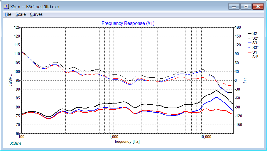
The difference between using a 1 or 1.6 mH coil is not big, but it helps to reduce the slightly hot area around 1 kHz. I'll need to experiment with the notch values so that I don't make the sound dull off-axis.
/Anton
Attachments
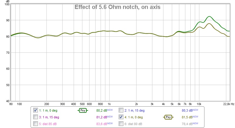
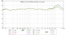
Result with notch and new BSC
Now I've finalized the filter. The off axis (15 deg) response caused me to make the notch a little shallower to reduce the risk of making the sound dull. Instead of a 3.3 Ohm I chose a 5.6 Ohm resistor. Here is a comparison on axis, 1 m distance, ~2 m above ground:
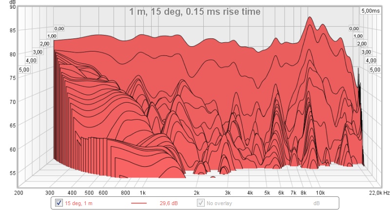
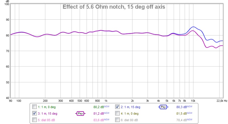
And here 15 deg off axis:
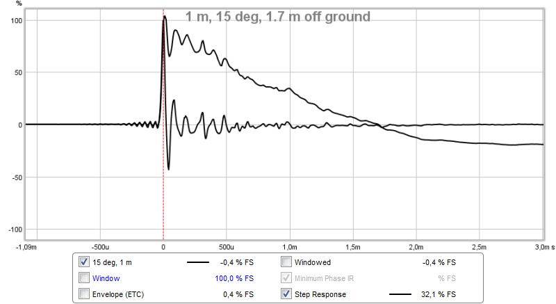
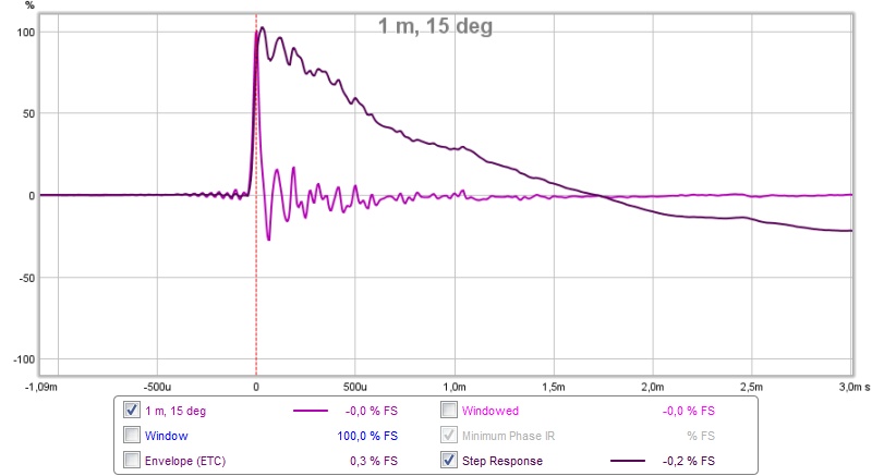
Here is the impulse/step response 15 deg off axis:
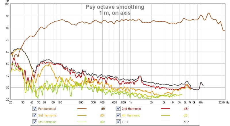
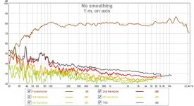
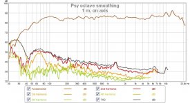
And distortion (80 dB):
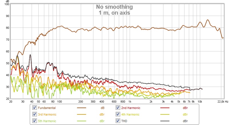
and at 85 dB:
This (the sweep) sounds fine to my ears, but when I run a sweep at 90 dB there is some obvious noise below 100 Hz.
I also made a ground plane measurement to see how the LF area behaves (in half space):
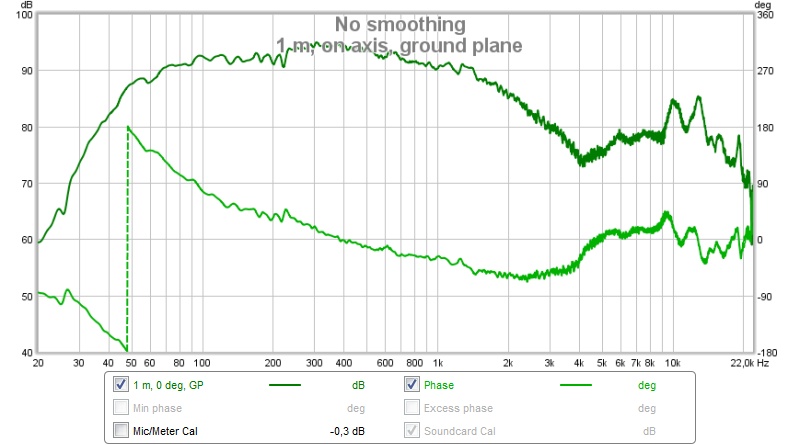
It definitely reaches below 50 Hz, I'm satisfied with that.
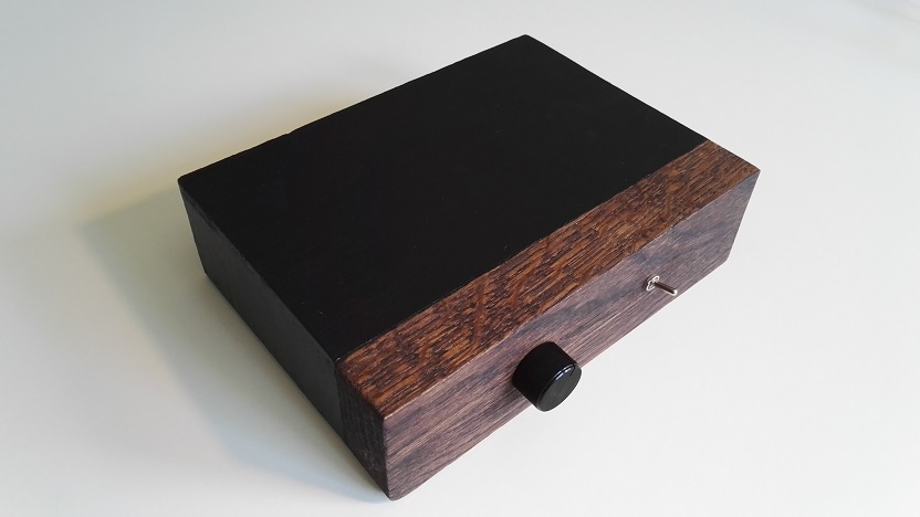
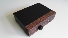
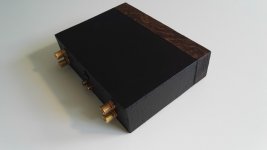
I've built a small box for the filter and amplifier out of a scrap piece from my media console build and some plywood:

Tomorrow is the big test when the complete setup will play background music for my 30th birthday 🙂
/Anton
Now I've finalized the filter. The off axis (15 deg) response caused me to make the notch a little shallower to reduce the risk of making the sound dull. Instead of a 3.3 Ohm I chose a 5.6 Ohm resistor. Here is a comparison on axis, 1 m distance, ~2 m above ground:
And here 15 deg off axis:
Here is the impulse/step response 15 deg off axis:
And distortion (80 dB):
and at 85 dB:
This (the sweep) sounds fine to my ears, but when I run a sweep at 90 dB there is some obvious noise below 100 Hz.
I also made a ground plane measurement to see how the LF area behaves (in half space):
It definitely reaches below 50 Hz, I'm satisfied with that.
I've built a small box for the filter and amplifier out of a scrap piece from my media console build and some plywood:
Tomorrow is the big test when the complete setup will play background music for my 30th birthday 🙂
/Anton
Attachments
-
 IMG_20160812_141506.jpg61.6 KB · Views: 342
 -
 IMG_20160812_141440.jpg52.3 KB · Views: 338
 -
 notch on axis.jpg65.4 KB · Views: 350
 -
 Impulse.jpg60.2 KB · Views: 342
 -
 dist 80 dB.jpg98.8 KB · Views: 364
 -
 dist 85 dB.jpg99.4 KB · Views: 748
 -
 ground plane.jpg85.4 KB · Views: 352
 -
 notch 15 deg.jpg66.9 KB · Views: 364
Thanks!
Nice amp (what was inside?)!
Nice response!
The amp is a TPA3116 like this:

The linear pot is modified according to sound.westhost.com to make it near logarithmic.
Air coil (Jantzen 20 AWG) inductors, ceramic resistors, WIMA mkp caps.
/Anton
- Status
- Not open for further replies.
- Home
- Loudspeakers
- Full Range
- CHR-70 gen. 3 in folded MLTL