You don't have .01 uf ceramic caps across the electrolytics after either bridge. Rectifier diodes produce sharp edges of 0.7 v as they turn on & off, these round those out. On every dynaco product I own. Rated at 1000 PIV since spikes on AC lines can hit 1300 v from shutoff of heating/air motors.
The big electrolytics have so much self inductance from being wound up that the capacitance in the megahertz is very low.
Thanks indianajo, there are so many opinions on bypassing electrolytics, I have read so may posts on where they should be placed, i should probably put 10nf caps across the 4 diodes, then there is the opinion to use a cap+resistor across the AC before the bridge, snubber this and that, Its a real can of worms, I would like to nail why this time my SRPP is noisy and it never was, maybe I have connected the 0V wires differently, its been a few years since I did this last but ive never used bypass caps on the heater reservoirs?
Oh and ive never used ceramics, always polyprop films for bypass, another can of worms....
Last edited:
Well, dynaco used .01 without the snubber resistor, got away with it. They only used the one after the bridge. The hum is lower than the signal/noise of CD's that were invented 12 years after the PAS2 & ST70 were designed.
To be completely picky you can put 10 ohm and a .01 across each diode, but we are not designing 120 db s/n mastering boards here.
BTW I have a MOS suppressor installed in my ST-120 after the fuse and before the transformer, and I still get pops in the speaker in a lightning storm if a strike is closer than 1.5 mile away (1.5 sec). Happened last weekend. In Kansas in 1983 I had a .01 ceramic cap vaporize in a lightning storm while I was at work. The one in the PAS2. The strike carbon tracked the power switch and left it permanently on. Transformer & tubes were fine.
Last edited:
Well, dynaco used .01 without the snubber resistor, got away with it. They only used the one after the bridge. The hum is lower than the signal/noise of CD's that were invented 12 years after the PAS2 & ST70 were designed.
To be completely picky you can put 10 ohm and a .01 across each diode, but we are not designing 120 db s/n mastering boards here.
BTW I have a MOS suppressor installed in my ST-120 after the fuse and before the transformer, and I still get pops in the speaker in a lightning storm if a strike is closer than 1.5 mile away (1.5 sec). Happened last weekend. In Kansas in 1983 I had a .01 ceramic cap vaporize in a lightning storm while I was at work. The one in the PAS2. The strike carbon tracked the power switch and left it permanently on. Transformer & tubes were fine.
I will give it a try but I will eat my hat if the source of my hum is due to me not having a 10nf cap across the first cap after both my bridge rectifiers! 😀
Just a general note: don’t use low ESR caps in a CRC as they induce higher ripple current. Select cap ripple current at (120Hz or 100Hz) so that ripple current rating is 2x quiescent current is a good rule of thumb. Also, bigger is not always better for cap sizing as too much capacitance may cause too much ripple current dieting charging cycle. Best way is to simulate on LTSpice or other software to check ripple and ensure is less than the rated ripple current spec.
Just a general note: don’t use low ESR caps in a CRC as they induce higher ripple current. Select cap ripple current at (120Hz or 100Hz) so that ripple current rating is 2x quiescent current is a good rule of thumb. Also, bigger is not always better for cap sizing as too much capacitance may cause too much ripple current dieting charging cycle. Best way is to simulate on LTSpice or other software to check ripple and ensure is less than the rated ripple current spec.
Many thanks for that, and there was me thinking that table I uploaded was all I needed, im almost done on my new power supply, I will post the result when i fire it up.....
...don’t use low ESR caps in a CRC as they induce higher ripple current. ...
Example, please?
Cap ESR will normally be swamped by transformer impedance, so low ESR will only cause a minor increase in ripple current. However, low ESR may cause a significant reduction in ripple voltage - which is surely what we want?
The caps I'm installing now are rated at 435ma ripple current, is that good? Bad? I don't think there's so much choice when you get up to 400v.
435mA ripple rating is good if you have 300mA ripple current; it is bad if you have 600mA ripple current. What does PSUD2 tell you?
To be honest I have just googled that to see what it is, I will download it tonight and see how it works, thanks for that!
435mA ripple rating is good if you have 300mA ripple current; it is bad if you have 600mA ripple current. What does PSUD2 tell you?
Ive downloaded the software, this is going to be a learning curve and could take a while, I dont even see my rectifier on the download list, I will have a read of the "how to" if there is one....
I managed to cobble something together, just been clicking on stuff! unfortunately there are a lot of parameters I just dont know, Ive looked at the data sheet for the caps and the bridge and I cant find things like internal R of caps. I tried to create my own bridge but again so much info is missing from the data sheet that i can see, so i left things as they are and ran a sim, I couldnt work out how to add bypass caps, kept telling me it was not allowed or words to the effect of... so ive uploaded the results, I cant see the ripple current because I have no clue what I am looking at sorry. I dont even have details for my transformer, I changed it to 180v which I did measure to be correct, im getting about 280 so probably a bit more than 5%. I couldnt really draw it correctly either, its drawn as one channel but I increased the load to allow for 2....
Attachments

Bypass caps don't materially affect ripple current, so no need to include them in the model.
The ripple current figure you want is I(C1) RMS, so 319mA. However, this looks rather high for a DC draw of only 4mA. The reason is that PSUD2 has included the startup inrush current in the calculation. Put the 'reporting delay' up from 0 to 2 seconds and run it again.
The ripple current figure you want is I(C1) RMS, so 319mA. However, this looks rather high for a DC draw of only 4mA. The reason is that PSUD2 has included the startup inrush current in the calculation. Put the 'reporting delay' up from 0 to 2 seconds and run it again.
Bypass caps don't materially affect ripple current, so no need to include them in the model.
The ripple current figure you want is I(C1) RMS, so 319mA. However, this looks rather high for a DC draw of only 4mA. The reason is that PSUD2 has included the startup inrush current in the calculation. Put the 'reporting delay' up from 0 to 2 seconds and run it again.
I should of saved that shouldnt I, lol, OK, good info, I will draw it again...
Just a general note: don’t use low ESR caps in a CRC as they induce higher ripple current. Select cap ripple current at (120Hz or 100Hz) so that ripple current rating is 2x quiescent current is a good rule of thumb. Also, bigger is not always better for cap sizing as too much capacitance may cause too much ripple current dieting charging cycle. Best way is to simulate on LTSpice or other software to check ripple and ensure is less than the rated ripple current spec.
And low ESR caps are going to be rated for higher ripple current... I disagree and would use them, especially having R in series.
16mA ripple for 4mA DC sounds more plausible.
So the caps are good, excellent.....
...just been clicking on stuff!....
For a measly 4mA? Forget about it!!
OK, you started PSUD fine. But plot the load voltage V(I1). It has only got to 200V at the end of one second, we expect like 250V. We really hardly care about the first second(*): a cap won't blow-up that fast, and the music hasn't started. Let the load voltage stabilize. "Many RC." 100u+330r is 0.03 seconds, but you have three of these, so several seconds.
BTW: this is why you have different current in R1 R2 R3, when they clearly must be the *same* current steady-state (operating). In the first few seconds the caps are still charging. I get about the same numbers as you, but this is not the running condition.
I found voltage still rising at 2 seconds, so I ran for 7 seconds (second image). The current has narrow 80mA peaks, the RMS is 16mA. This is what I would expect: cap ripple current "several times" load current. 4mA * several is 16mA.
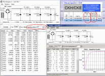
What can the cap stand? I have extracted a piece of a datasheet of a good $3 capacitor (1st image). We see the ESR is really more like 3.3r, not the 2r default; we could either claim that 3.3 is Max and Typ may be 2, or re-run the sim with 4 Ohms (because ESR rises with age) just to be sure nothing bad happens. (It won't.) Also we see that caps of this rating, size, and price can stand 300mA of ripple current, FAR more than you need. (Ripple goes mostly with size, to shed heat, but also with ESR but note that you can't buy much lower ESR in an aluminum electro cap.)
(*) We DO care about the first cycle when picking a diode. The turn-on current can approach V(T1)/R(source) or 250/30 or 8 Amps. PSUD figures 4A first halfwave, 1.6A next, declining to that 80mA peak noted steady-state. The 1Amp 1N400x will take the 4A one-time peak comfortably. (Pick your diode >2X the DC load and you will usually be OK. This says you need a >0.008A diode, which is no cheaper than a 1N4007.)
Attachments

For a measly 4mA? Forget about it!!
OK, you started PSUD fine. But plot the load voltage V(I1). It has only got to 200V at the end of one second, we expect like 250V. We really hardly care about the first second(*): a cap won't blow-up that fast, and the music hasn't started. Let the load voltage stabilize. "Many RC." 100u+330r is 0.03 seconds, but you have three of these, so several seconds.
BTW: this is why you have different current in R1 R2 R3, when they clearly must be the *same* current steady-state (operating). In the first few seconds the caps are still charging. I get about the same numbers as you, but this is not the running condition.
I found voltage still rising at 2 seconds, so I ran for 7 seconds (second image). The current has narrow 80mA peaks, the RMS is 16mA. This is what I would expect: cap ripple current "several times" load current. 4mA * several is 16mA.
What can the cap stand? I have extracted a piece of a datasheet of a good $3 capacitor (1st image). We see the ESR is really more like 3.3r, not the 2r default; we could either claim that 3.3 is Max and Typ may be 2, or re-run the sim with 4 Ohms (because ESR rises with age) just to be sure nothing bad happens. (It won't.) Also we see that caps of this rating, size, and price can stand 300mA of ripple current, FAR more than you need. (Ripple goes mostly with size, to shed heat, but also with ESR but note that you can't buy much lower ESR in an aluminum electro cap.)
(*) We DO care about the first cycle when picking a diode. The turn-on current can approach V(T1)/R(source) or 250/30 or 8 Amps. PSUD figures 4A first halfwave, 1.6A next, declining to that 80mA peak noted steady-state. The 1Amp 1N400x will take the 4A one-time peak comfortably. (Pick your diode >2X the DC load and you will usually be OK. This says you need a >0.008A diode, which is no cheaper than a 1N4007.)
Really appreciate you running the software, I have a long way to go before I can really understand everything your saying, I hate not being able to grasp it. The bridge rectifier I choose in the sim is probably nothing like what Im using, I did have MUR 820's but then I realised they where only 200v so I have now rebuilt it with a GBJ2510, 1000v 25A. My transformer is pushing 280vDC after rectification. Im not even sure I need to run sims as I just want to build a very quiet power supply using just a CRC type filter. I am thinking of getting 300r's so I can add an extra cap but I have no clue how good this supply is.
- Status
- Not open for further replies.
- Home
- Amplifiers
- Power Supplies
- choosing capacitors for a crc filter