I always use 0.1uf which JLH used (and others ) read professional engineering website which agrees -
Where did the value of 0.1uF for bypass capacitors come from? - Electrical Engineering Stack Exchange
Where did the value of 0.1uF for bypass capacitors come from? - Electrical Engineering Stack Exchange
https://www.mouser.ca/ProductDetail/WIMA/MKP1G031004D00MSSD?qs=OanN%252B0kfw%2FbwjbqvfFcR%2FQ%3D%3D
So be it then!
Regards,
Dan
So be it then!
Regards,
Dan
Ceramic capacitors are recommended in very small values for audio use and are know as =COG ceramic --LOW K--D=0.001 larger values about 400pf (approx ) are not recommended due to various technical issues therefore post #3 is correct as Polypropylene film capacitors are my recommendation as well as JLH and others.
"Ceramic capacitors......0.001 larger values about 400pf (approx ) are not recommended due to various technical issues..... Polypropylene film capacitors are my recommendation as well as JLH and others"
Please specify exactly WHAT "technical issues" you are referring to. 100nF ceramic MLCC X7R are recommended by Rod Elliott.
Please specify exactly WHAT "technical issues" you are referring to. 100nF ceramic MLCC X7R are recommended by Rod Elliott.
Ceramic capacitors can be put into 4 groups-
1=low K
2=medium K
3=high K
4=monolithic
A value of 0.1uf equates to high K ,
a tolerance of -20% to +80%,
a temperature coefficient of +22% to -82%
and a D of 0.2
Leakage resistance is classed as high ,
stability is classed as "fair "
not a type of capacitor I would fit in an audio circuit .
I praised COG ceramic but there is a world of difference between them and other types and values as COG applies to the lowest capacitance range .
What I have posted is scientific /technical standards on ceramic capacitors but times change have they been scrapped or a new type of previous unobtainable ceramic found ?
Are you recommending a 50V rated cap for this application? POOF!?
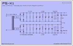
I would say that there is nothing to "bypass" in power supply at all, so there is no need in bypass caps in here.I'm building a power supply very similar to the one seen below for my monster Class A amplifier. My question is, what is the accepted practice or calculation for choosing a bypass cap value? I've seen all the way from .1uF to 10uF.
- Home
- Amplifiers
- Power Supplies
- Choosing Bypass Cap for Linear Supply?
