You just have to look at the schematic to see it needs -+24v power supply.
There probably is a way to take a +24v switchers and use a bridge and soothing caps to get a -24v out of a +24v switcher but I don't know how to do that without looking it up somewhere. Why go thru that if something already exists to solve your problem?
That's why I posted the Meanwell, cause it has both -+24v.
I used switchers and they don't sound as good as linear in a simple circuit like this. Used one for a long time on the original B1. Super Reg is superior. Sorry. Just is. You want to just get it done, use a switcher.
Last edited:
I see in post #17 Unipolar PSU as source , then bipolar made of it
observe where GND is
so , logical , 24Vdc switcher - used to make +/-12Vdc
observe where GND is
so , logical , 24Vdc switcher - used to make +/-12Vdc
I see a +V and a -V before the large caps, but ok, I'm not going to argue with you, because I'm probably wrong.
Does -V go to ground at the switcher?
Does -V go to ground at the switcher?
Where, prey tell.... is that recommended? 😕
Mr. Pass stated that he used a single 24v switcher.
TIA, and please pardon my confusion.
It's in the schematic. You may be confusing this with the standard B1, which is single-ended.
Last edited:
I think they mean before the B1 and before the power supply with the caps tide to ground.
I just don't understand how a switcher with +24v and a ground connects to +V and -V. Isn't -V more negative than ground?
I just don't understand how a switcher with +24v and a ground connects to +V and -V. Isn't -V more negative than ground?
I don't get it either, but the Salas shunt sounds so good I don't know why you'd bother with a switcher.
GND is , besides being state of mind , matter of choice
it is where you put it
look at schematic (#17)
prior to gnd , you have positive and negative sides of PSU (switcher or not , irrelevant) , neither of these being GND
anyway , everything is drawn on schematic
and - nobody is saying that you can't use regular and usual bipolar PSU ..... what's shown here is (nothing more but also nothing less) than neat way of cheapskating ........
I wouldn't use a switcher either. My concern was with the voltage and polarity applied to the circuit. I am designing in a psu of my choosing, and it is a +24v supply.
I was surprised by Mr. Pass' reply that he used a single supply. It then became apparent to me that the divider on the right of the schematic takes care of the split. I'm thinking you could ditch the whole divider and run a dual supply whatever flavor you like within V limits. NP probably designed it as a drop in to possibly replace the B1 still with +24v only (conjecture).
I don't care about being right, I just want to get it right 🙂
edit: Choky, you type too fast
I believe with a single 24VDC supply you will create (as ZM has said)
a +/-12V supply with a virtual ground.
My concern with using +/-24VDC rails is that at high voltage swing can exceed
the 2sj74's official 25VDC Vds rating. (I think Mr Pass has said they can take
somewhat more voltage though.)
A question I have is that with the 50ohm trimmer providing degeneration
and nulling dc offset, how much current are we passing through the jfets?
I wonder how high idss can we use before dissipation becomes an issue?
Thanks,
Dennis
you can always count that Papa is assuming/meaning BL range (6 to 12mA) and if not , it will write note , big enough .
prior to gnd , you have positive and negative sides of PSU (switcher or not , irrelevant) , neither of these being GND
anyway , everything is drawn on schematic
and - nobody is saying that you can't use regular and usual bipolar PSU ..... what's shown here is (nothing more but also nothing less) than neat way of cheapskating ........
Well there you have it. Sorry if I lead anyone down the wrong path.
Serves you right for listening to me. 😛
Last edited:
GND is , besides being state of mind , matter of choice
it is where you put it
look at schematic (#17)
prior to gnd , you have positive and negative sides of PSU (switcher or not , irrelevant) , neither of these being GND
anyway , everything is drawn on schematic
and - nobody is saying that you can't use regular and usual bipolar PSU ..... what's shown here is (nothing more but also nothing less) than neat way of cheapskating ........
So you mean a virtual ground, right? I used to use those for headphone amps.
I believe with a single 24VDC supply you will create (as ZM has said)
a +/-12V supply with a virtual ground.
My concern with using +/-24VDC rails is that at high voltage swing can exceed
the 2sj74's official 25VDC Vds rating. (I think Mr Pass has said they can take
somewhat more voltage though.)
A question I have is that with the 50ohm trimmer providing degeneration
and nulling dc offset, how much current are we passing through the jfets?
I wonder how high idss can we use before dissipation becomes an issue?
Thanks,
Dennis
I see what you mean about only getting +/-12V from a switcher. I don't know about worrying about the +/-24V supply though - the circuit has no gain and even the most vigorous source I have (or had until I switched tubes) could only swing +/-10V. As for Idss, mine are 9.3mA - I'll post if I run into any problems. Haven't put the IR gun on them yet.
Yeah, it's probably more of a concern if one tries putting this directly after
something with high output, like the BA3 front end.
I am using the B1 so I'm naturally looking forward to trying this revision.
Cheers,
Dennis
something with high output, like the BA3 front end.
I am using the B1 so I'm naturally looking forward to trying this revision.
Cheers,
Dennis
Actual testing of the parts reveals fairly high breakdown voltages, as I
recall in the 40+ volt range.
Nevertheless, I would not expose them beyond about 30 volts or so.
😎
recall in the 40+ volt range.
Nevertheless, I would not expose them beyond about 30 volts or so.
😎
Depending on the project it will or wont matter what the value is.
As others have said its the capacitor value and input impedance that set the breakpoint frequency f=1/(2 pi r c)
If you are using record decks then you can get very low frequency rumble signal. In this case its worth setting the breakpoint above what the rumble frequency is.
As others have said its the capacitor value and input impedance that set the breakpoint frequency f=1/(2 pi r c)
If you are using record decks then you can get very low frequency rumble signal. In this case its worth setting the breakpoint above what the rumble frequency is.
At +/-24V (actually a little less after the resistors) and after playing for 30 minutes or so my transistor pairs aren't much above ambient - about 38-39º, but the case is hot from the Salas shunt and it's sitting on an M2, which doubles as a sort of space heater, so I don't think dissipation will be a problem.
Actual testing of the parts .......
Easily stated by the man who owns the remaining global stockpile 😉
B1 R2 finished
The case is a cheap one I bought on ebay from some guy in Hong Kong - it fills the bill and looks pretty decent. I jerry-rigged some LEDs to make a lighted power switch. The relay input-switching works well, now that I have the coil wired right! It doesn't work if you wire it backwards, I found out to my surprise. I replaced the transformer bolt with a nylon one on the advice of Vince D, and also lifted the transformer off the case floor about a quarter inch. Don't know whether it made a difference - too long between before/after, and I also replaced the pot. In any case it's the cat's meow now.
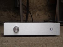
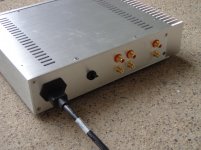
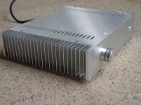
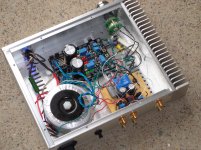
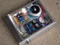
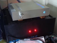
The case is a cheap one I bought on ebay from some guy in Hong Kong - it fills the bill and looks pretty decent. I jerry-rigged some LEDs to make a lighted power switch. The relay input-switching works well, now that I have the coil wired right! It doesn't work if you wire it backwards, I found out to my surprise. I replaced the transformer bolt with a nylon one on the advice of Vince D, and also lifted the transformer off the case floor about a quarter inch. Don't know whether it made a difference - too long between before/after, and I also replaced the pot. In any case it's the cat's meow now.


Last edited:
- Home
- Amplifiers
- Pass Labs
- Choosing best output coupling capacitors for B1