Hi, BudP -
I've decided that for my latest project, I'd probably want to go a step up from a standard Edcor/Hammond offering even at twice the price. I have also come across information relating to the Music Reference RM-10 and I am thinking of applying the same sort of bias conditions to the output 7189's except that I would probably go about 5 - 10 ma grid drive into AB2 because I plan to DC couple the amp internally so may be looking at as much as 50 watts/side here. I was therefore thinking a 50W 10KCT/4/8/16 with UL taps output transformer optimized for extended bandwidth and optimal detail retrieval with slightly higher distortion allowable as a tradeoff since I should have plenty of OL gain available & plan to use both local and global feedback loops. Because of the DC coupling and the MR-type output stage biasing, the primary winding may approach 900Vdc average referenced to the amplifier ground. I was considering the UL taps to provide the local feedback source instead of UL operation (amp topology is fully balanced). Does such an OPT sound doable to you?
After seeing a comment earlier in this thread about the deleterious effects of DC unbalance at the output stage, I am seriously considering adding an active balancing circuit that should be capable of keeping the average DC balance within a few percent. Such a circuit seems like probably a good idea with a DC coupled tube amp, anyway.
Last edited:
I am unsure of what you are referencing when you mention the RM10 amplifier information you have come across. This amp is a single ended EL 34 driven by a 12AX7 driver stage. How does this relate to an amplifier built with a 7189 tube? From looking at the tube specs, I am assuming your 900vdc is what you are adding together, from CT to plate on two tubes, in a push pull configuration, is this correct?
In a general sense, you do not need global feedback and local feed back and an ultralinear tap. You can run all three of these, but I do think you will find the sound to be less dynamic and musical, than you might be hoping for.
Our push pull outputs, in level one which sounds like what you are asking for, are flat in phase and frequency response from 20 Hz to 40 kHz at any power level and are designed for very high retention of small signal coherence, but I would not consider them "wide band" in comparison to outputs that have had their coupling reduced so that they can have excursion out to 100 kHz at some point in their power level range.
For any further discussions you really should PM me.
Bud
I am unsure of what you are referencing when you mention the RM10 amplifier information you have come across. This amp is a single ended EL 34 driven by a 12AX7 driver stage. How does this relate to an amplifier built with a 7189 tube?
Roger Modjeski's RM-10 amplifier is an EL84/6BQ5 based amplifier. He describes the key operating parameters (B+, bias, idle current, load, etc.) in a thread here:
diytube.com :: View topic - How many watts from a pair of EL84's?
Since the 7189 is "the same" as a 6BQ5 (only better), it is entirely relevant. It sounds like a neat amp. Hope I'll see one some day...
I think the RM-9 is the EL34 amp.
Last edited:
Hi, BudP -
After seeing a comment earlier in this thread about the deleterious effects of DC unbalance at the output stage, I am seriously considering adding an active balancing circuit that should be capable of keeping the average DC balance within a few percent. Such a circuit seems like probably a good idea with a DC coupled tube amp, anyway.
Don't worry, properly engineered transformer will handle this issue without problem (+/-10% idle current discrepancy) 🙂 This is one of the parameters which distinguishing professional design.
If you are perfectionist, as far as I remember one of the Carver tube amps had self-bias balancing feature. But I may be wrong here.
Last edited:
an increasing problem as my cornea's age.
For those of you who might worry about Bud winding your transformers with an aging set of corneas, it is actually Mrs. Bud who does the manufacturing... i assure you Bud's ears are first rate thou 🙂
dave
From looking at the tube specs, I am assuming your 900vdc is what you are adding together, from CT to plate on two tubes, in a push pull configuration, is this correct?
Roger Modjeski claims that the 7189 can be safely operated with a plate supply voltage of 700Vdc, if the screen grid is kept half of that. The DC coupling scheme I am considering would basically 'stack' this voltage on top of an approximately 150Vdc input stage plate voltage where I am planning to use a long tailed pair of high gm sharp cutoff pentodes as the input/drivers. This would give approx. 850Vdc at the transformer primary compared to the secondary. The peak voltage referenced to ground at clipping would probably be in the vicinity of 1500V. Roger claims that at 30mA per pair quiescent, fixed bias, the RM10 operates the 7189s cooler than a Dynaco Stereo 35 does.
This may sound overly optimistic, but a pair of the EL34 in PP can generate up to 100Wrms with 800V plate, 400V screen, so why not give it a try? Try biasing like an RM10 but with a little lower primary transformer impedance and a little positive grid drive. If I start blowing tubes, I'll just swap in a lower secondary voltage power transformer and/or AC couple the driver to the output stage.
Last edited:
OK, so I am still a bit confused about the actual load into the transformer. If it is to be SE then I need to know the actual DC current that will flow across the primary winding. Since you are referring to a concern about offset current in the core, I am still confused as this is only a concern with a push pull tube arrangement. Our OPT's will be balanced to within 1.5 ohm and the primary DCR should not exceed 100 ohms end to end, so a 1% imbalance from a center tap, which a SE OPT will not have. May I see a circuit diagram please?
Bud
Bud
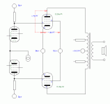
Sorry if I left the impression that it might be SE. Planet 10 is right. It's definitely PP. I can work up a schematic diagram, but it'll look like a disaster waiting to happen, what with DC coupling and all. I plan to use protection features such as cutting the 7189 screen grid voltages to zero using series pass SS devices (mostly high voltage MOSFETS such as some TO220 'fullpack' 1000V N channel devices I have with integral gate clamp zeners) if the input stage hasn't warmed up or is missing, as well as using neon bulb 'clamps' to prevent excessive positive 7189 grid excursion. Also, there would be a circuit to maintain the correct grid bias for the output stage tubes by changing the long tailed pair current. Hopefully an 'auto balance' circuit could be implemented around an isolated op amp such as the TI/Burr Brown ISO124 controlling the input pentode screen grid voltages in a 'seesaw' manner by comparing the individual 7189 plate currents. The trick here would be keep the balance circuit sonically transparent as much as possible because without considerable LP time constant smoothing & maybe some non-linear shaping it would attempt to cancel the signal to be amplified! To keep SS grit from these protection/bias circuits from affecting the sound much, I'm thinking of bypassing all screen grids using RC networks with polypropylene capacitors.
Last edited:
Thanks Dave.
I must admit to being concerned about our skill set with plate voltages above 700 vdc. This will be a fairly large transformer any way, what with 76 henries required for -3 dB operation and 212 henrries required for - 0.5 dB so there will be enough room to build in the extra dielectric creepage and clearance requirements.
I am a bit pressed for time at the moment so let me think about this for a few days. Meanwhile perhaps Johan would like to chip away at the math?
Bud
Hi, Dave -
Wow! That's quick. That's pretty close to what I was thinking of, except the 7189 cathodes will be referenced to ~+150Vdc (B3+) instead of ground to allow biasing of the input stage. I have a few options that I'll look at/try, regarding sourcing the input stage plate supply - I was thinking that a R divider between the UL taps or possibly the output plates and ground could provide a way to get some local feedback while leaving a little gain for any loop feedback desired. There is also the option of taking balanced loop feedback, of course, with the 4 ohm tap grounded and fb being taken from the ground and 16 ohm taps, but I really haven't thought that part through very much. I'm sure some combination of the above should be useful though. What do you think?
Wow! That's quick. That's pretty close to what I was thinking of, except the 7189 cathodes will be referenced to ~+150Vdc (B3+) instead of ground to allow biasing of the input stage. I have a few options that I'll look at/try, regarding sourcing the input stage plate supply - I was thinking that a R divider between the UL taps or possibly the output plates and ground could provide a way to get some local feedback while leaving a little gain for any loop feedback desired. There is also the option of taking balanced loop feedback, of course, with the 4 ohm tap grounded and fb being taken from the ground and 16 ohm taps, but I really haven't thought that part through very much. I'm sure some combination of the above should be useful though. What do you think?
Last edited:
except the 7189 cathodes will be referenced to ~+150Vdc (B3+) instead of ground to allow biasing of the input stage.
I originally had them tied to ground, but put the resistors/black boxes back in as i new you'f need to chewup that 150 V somewhere.
What do you think?
I'm still a rookie at this, i know just enuff to get myself in trouble 🙂
dave
I updated the simple schematic in post 91.
Thoriated, if you want to flesh this out more, i'm intrigued by the project and would be happy to make pretty pictures, all you'd need to do is feed me sketches (or simple instructions)
And if Bud made the only OPTs for a giant-killer amp that wouldn't hurt either.
dave
Thoriated, if you want to flesh this out more, i'm intrigued by the project and would be happy to make pretty pictures, all you'd need to do is feed me sketches (or simple instructions)
And if Bud made the only OPTs for a giant-killer amp that wouldn't hurt either.
dave
I've been pondering a headphone amp SE design. I understand that a gapped (SE) transformer may have sonic drawbacks vs a parafeed (P-P) transformer if the gap is too large. Where do you draw the line? I am looking at a 45 ma DC SE transformer, at this high current(for a headphone amp) would I be better off to parafeed?
The DC current is only part of the question. The rest is , what tube are you looking at and are you intent upon Pentode or triode. The decider is how much gap vs how much inductance is required. In a headphone amp this inductance has to be correct at very low signal levels and these are unlikely to provide enough flux to get very far up the permeability curve.
Without that aid we end up with large transformers, or very high perm core material, which has it's own problems.
45 ma DC is not in and of itself a decision point, we need more info please.
Bud
Without that aid we end up with large transformers, or very high perm core material, which has it's own problems.
45 ma DC is not in and of itself a decision point, we need more info please.
Bud
A question regarding transformer steel. A bit of a thread hijack again but since there are people here that really know this stuff, I figured this was the best place to ask. As I mentioned above, I am looking to build a motor growler. A growler is a diagnostic device to ***** the conditions of motor winding. It basically acts as half a transformer with the motor rotor, or stator completing the magnetic circuit. These are available and come up on E-bay all the time but they are like tube testers. Everyone is looking for them and they get bid up to ridiculous prices. Even worse, they come out of repair shops where they have probably been abused and who knows if they still work. I have a very nice book on their design and construction and everyone always likes a challenge ;-)
Anyways, as part of a lab remodel, we have been kicking around a box that has sat in the corner for years. It was destined for the scrap metal pile. I never paid any attention to it until today, since it was in the way once again. I looked at the box, as I was moving it, and it was labeled M6. Doh! It contains 60 pieces, 12-3/4" square, with a 2" hole on the center and a 3/8" hole in the corners. 60 pieces, It is actually labeled 29M6 so my guess is that it is .29mm perhaps. I have to go down to the shop and measure thickness.
So a bit round about (and I apologize for the hijack) but my question is how should it be cut? Does anything need to be done after it is cut? It says on the box that they were laser cut. Can it be cut with a wire EDM or water jet? I assume a plasma cutter may alter the material characteristics.
Tough question. The very best magnetician to ask that question of would be Tom Thomas of Temple Steel. Best way to get hold of Tom is to call (773) 250-8000.
In a general sense anything that heats the metal will alter the permeability. The lamination's made from 29 gauge (0.014"thick) M6 are stamped at a very high speed and annealed immediately afterward. This is a very brittle metal and must be thin due to that. I suspect water jet is your best bet. It might be necessary to have the parts re-annealed anyway, due to the laser cutting. Best to ask Mr. Thomas about that and I would ask him who he would recommend and only go there. This man is the worlds foremost magnetician and a very down to earth kind of guy.
Bud
- Status
- Not open for further replies.
- Home
- Amplifiers
- Tubes / Valves
- Choosing an output transformer