625VA transformer is suitable for supplying a total maximum power of 300W to 625W.
Two channels of 150W is OK.
Two channels of 200W is OK.
Two channels of 250W is OK.
Two channels of 300W is OK.
All of those design targets will work well on a 625VA transformer, provided you select the correct voltage for your speaker impedance.
Two channels of 150W is OK.
Two channels of 200W is OK.
Two channels of 250W is OK.
Two channels of 300W is OK.
All of those design targets will work well on a 625VA transformer, provided you select the correct voltage for your speaker impedance.
Ha!!! You guys are trouble makers.😀
Now I just feel I should give up the clearance transformer and get the 35V 35V transformer at regular price to get +/-50V rail!!!!
Now I just feel I should give up the clearance transformer and get the 35V 35V transformer at regular price to get +/-50V rail!!!!
Hi
I just dug up this old thread. I since bought the 30V 30V transformer. due to a temporary contract, I have not done much until lately. Continue on with the idea of using over 200mA per stage so I can get almost 10W of class A power. I am actually thinking of getting a lower voltage transformer.
I found this one:AN-5222 - 500VA 22V Transformer - AnTek Products Corp
This is 22V 22V which gives 31VDC-31VDC. So it's a 30V-30VDC after rectifier.
1) If I have 5 pairs of EF each biased at 300mA. I have 1.5A idle current and 3A of Class A current.
2) For 4 ohm speaker, Class A voltage is 3A X 4ohm=12V. Power output is 0.5 X 12V X 3A= 18W of class A power.
3) for 8 ohm speaker, Class A voltage is 3A X 8ohm=24V. Power output is 0.5 X 24V X 3A=36W!!
4) Assuming I get 26V peak swing. from calculation, I will get 84W for 4 ohm and 42W for 8W.
5) Idle power dissipation is 1.5A X 62V=93W per side.
This looks like a very good deal!!! I know you guys think 150W is not good enough. Judging from tube amps, 84W power with 18W Class A power is plenty for a normal living room.
What do you guys think?
Too hot.
You have ended up with a ClassA amplifier capable of driving 8ohms: 42W in ClassAB, 36W in ClassA.
Increase the bias to just slightly over 325mA/pr and it will be a ClassA amplifier.
Minimum transformer roughly 6times to 10times the maximum ClassA power, gives you a 252VA to 420VA, 2*22Vac
Heatsink is required to dissipate ~100W and stay less than 20Cdegrees above Ta.
expect an Rth s-a of about 0.15C/W
That is an almighty heatsink and why I started with "too hot".
Too hot.
You have ended up with a ClassA amplifier capable of driving 8ohms: 42W in ClassAB, 36W in ClassA.
Increase the bias to just slightly over 325mA/pr and it will be a ClassA amplifier.
Minimum transformer roughly 6times to 10times the maximum ClassA power, gives you a 252VA to 420VA, 2*22Vac
Heatsink is required to dissipate ~100W and stay less than 20Cdegrees above Ta.
expect an Rth s-a of about 0.15C/W
That is an almighty heatsink and why I started with "too hot".
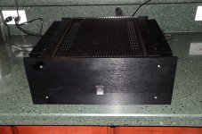
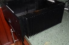
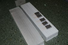
Attached are two pictures of my chassis and the heat sink. It's a big chassis with huge heat sink. I paid $280 between the chassis and shipping. Also, I include the picture of the heat sink used in my test platform. It's a smaller heat sink, but I am sure it's going to dissipate 100W from looking at the size respect to the big power transistors.
In fact, I think I am overkill with these heat sinks particularly when I put in the real chassis.
Yes, the link I showed is a 22V-22V 500VA transformer. I still have the option of using my other 30V-30V 625VA transformer also. But I have to lower the bias to 200mA per pair instead of 300mA.
The company also sell a 20V-20V and an 18V-18V 500VA transformer also. Then I can increase to 350mA and get Class A with 8ohm.
Attachments
Last edited:
That sink looks to be about 0.2C/W to 0.3C/W
It is too small for 100W and deltaT of <20Cdegrees.
It is too small for 100W and deltaT of <20Cdegrees.
That sink looks to be about 0.2C/W to 0.3C/W
It is too small for 100W and deltaT of <20Cdegrees.
You mean the smaller silver color aluminum one? Yes, I expect it to run hotter, but I think it's going to be ok for 100W. It's still a 12" X 2.75" X 1.4" big. It's not exactly a wimpy heat sink.
Regarding to the big chassis, I kind of remember when I bought the chassis, it said the heat sink was 200W per side. That one is a lot bigger. It's a 12" X 5.75" X 2", thick metal.
I finally have the time to start building the amp, it's a lot of work!!! Just finish stuffing a pair of OPS board, 4 IPS/VAS. Just send out the speaker protection board. Still designing the preamp electronics.
I am getting a little fancy, I just ordered a remote volume pot, I just layout the relay board for 3 DVDR inputs, still need to design the buffer board. I tell you, the money I spent, I am sure I can buy a second hand Threshold power amp and a nice preamp!!! But that will take away all the fun.
Last edited:
Alan0345. I am using passive heatsinks of approx. 16" x 5" x 2" per side and dissipating 67watts of heat per channel. They run at about 30C above ambient. I consider those to be very near the limit for safe operation. I should bear Andrew T advice in mind.
Alan
Alan
That sink looks to be about 0.2C/W to 0.3C/W
It is too small for 100W and deltaT of <20Cdegrees.
No, I am referring to the black sinks attached to the chassisYou mean the smaller silver color aluminum one? ..................
It is a big sinkIt's still a 12" X 2.75" X 1.4" big. It's not exactly a wimpy heat sink.
200W into a Rth s-a of 0.25C/W gives a deltaT of 50Cdegrees. That would be below the industry standard of 70C to 80C used by the heatsink manufacturers for rating their heatsinks. Rth s-a of 0.375C/W would hit deltaT=75Cdegrees exactly. Clearly that big heatsink has a far lower Rth s-a than 0.375C/W............it said the heat sink was 200W per side. ............It's a 12" X 5.75" X 2", thick metal.
But you must de-rate the standard deltaT=75C value of Rth s-a to your actual Ts-Ta heatsink temperature rise (deltaT)
Choose your maximum Ta.
Choose your maximum Tc.
Calculate your Tc to Ts temperature drop.
Use these values to determine the maximum heatsink deltaT (Ts-Ta).
Use the manufacturer's data to de-rate the sink Rth s-a to your operational deltaT.
This will let you predict the maximum power the sink can dissipate and maintain your desired Tcmax.
Once you have that information your can decide what power the output devices and drivers can input into the heatsink.
Using the 200W value and guessing does not get you close !
Last edited:
30 deg above ambient is not bad. Mine is shorter but wider. I use 5 pairs of power transistors so I do spread the heat over the full width.Alan0345. I am using passive heatsinks of approx. 16" x 5" x 2" per side and dissipating 67watts of heat per channel. They run at about 30C above ambient. I consider those to be very near the limit for safe operation. I should bear Andrew T advice in mind.
Alan
Your 16" is very long, do you manage to spread the heat evenly across the whole width or you have hot spot?
Another option is use 20V-20V 300mA and the dissipation is down to 84W, still 18W Class A.
No, I am referring to the black sinks attached to the chassisIt is a big sink200W into a Rth s-a of 0.25C/W gives a deltaT of 50Cdegrees. That would be below the industry standard of 70C to 80C used by the heatsink manufacturers for rating their heatsinks. Rth s-a of 0.375C/W would hit deltaT=75Cdegrees exactly. Clearly that big heatsink has a far lower Rth s-a than 0.375C/W
But you must de-rate the standard deltaT=75C value of Rth s-a to your actual Ts-Ta heatsink temperature rise (deltaT)
Choose your maximum Ta.
Choose your maximum Tc.
Calculate your Tc to Ts temperature drop.
Use these values to determine the maximum heatsink deltaT (Ts-Ta).
Use the manufacturer's data to de-rate the sink Rth s-a to your operational deltaT.
This will let you predict the maximum power the sink can dissipate and maintain your desired Tcmax.
Once you have that information your can decide what power the output devices and drivers can input into the heatsink.
Using the 200W value and guessing does not get you close !
easier is to use lower voltage transformer like 20V-20V or even 18V-18V. This does not change the Class A power, just the max Class AB power.
Also, I guess lower the current to say 250mA/pair is not the end of the world.
deltaT = 30Cdegrees is too hot.30 deg above ambient is not bad.............
Ta = 20°C is normal.
Ta summer could be anywhere from 25°C to 35°C
add on deltaT of 30Cdegrees to a Ta of 30°C gives a Ts of 60°C
Add on the deltaT of {Rth c-s * Pq} . I''ll guess ~10Cdegrees for Tc-Ts
This gives Tc~70°C
That is hot.
But with 5pr it is doable. Do the sums and predict the de-rated SOAR into reactive loads for Tc =70°C+-5C for tolerances.
Last edited:
My question is whether there is any negative effect on the sound quality when the rail is too low? If I use 18V-18V. I get 25V rail, if I keep 300mA/pair, that's 75W of dissipation. I still get 18W Class A.
If I lower to 250mA/pair, it would be 62.5W dissipation and 12W class A. This should be definitely safe.
Problem is I only get 55W total with 4 ohm speaker and ONLY 27.6W using 8ohm speaker, that's low by any standard.
Then If I lower the bias to 200mA/pair, I only get 10W Class A for 4ohm and 16W for 8ohm. BUT the power dissipation is only 60W using 22V-22V transformer. I'll get 85W with 4 ohm and 42W with 8 ohm speaker.
decision decision!!!
Yes, this is the point I was trying to make to Alan0354. With a larger heatsink than he wants to use and dissipating less heat than he intends I consider mine to be right at the safe limits. So far this Spring and Summer the sink is at approx. 55C, can still keep my hand on it.
Also I have found from experience thermally isolating the heatsinks from the rest of the chassis is well worthwhile for the other components .
Also I have found from experience thermally isolating the heatsinks from the rest of the chassis is well worthwhile for the other components .
I have been doing a lot of calculation compromising between heat, Class A power and class AB power. These two seems to be the best
A)This is 20V 20V which gives 28VDC-28VDC after rectifier
1) If I have 5 pairs of EF each biased at 250mA. I have 1.25A idle current and 2.5A of Class A current.
2) For 4 ohm speaker, Class A voltage is 2.5A X 4ohm=10V. Power output is 0.5 X 10V X 2.5A= 12.5W of class A power.
3) for 8 ohm speaker, Class A voltage is 2.5A X 8ohm=20V. Power output is 0.5 X 20V X 2.5A=25W!!
4) Assuming I get 25V peak swing. from calculation, I will get 0.5 X 25V X 6.25A= 78W for 4 ohm in class AB. And 39W for 8ohm load.
5) Idle power dissipation is 1.25A X 56V=70W per side.
Dissipation is a little higher than 67W, but I do have 12.5W of Class A and 78W class AB power(my speaker is 4ohm, so that's what matters).
do you think I can get away with the chassis I have with 5 pairs of MJL1302/3281?
B)This is 18V 18V which gives 25VDC-25VDC after rectifier
If the above is still not acceptable, how about this?
1) If I have 5 pairs of EF each biased at 250mA. I have 1.25A idle current and 2.5A of Class A current.
2) For 4 ohm speaker, Class A voltage is 2.5A X 4ohm=10V. Power output is 0.5 X 10V X 2.5A= 12.5W of class A power.
3) for 8 ohm speaker, Class A voltage is 2.5A X 8ohm=20V. Power output is 0.5 X 20V X 2.5A=25W!!
4) Assuming I get 22V peak swing. from calculation, I will get 0.5 X 22V X 5.5A= 60.5W for 4 ohm in class AB. And 30W for 8ohm load.
5) Idle power dissipation is 1.25A X 50V=62.5W per side.
This is definitely safe.
Let me know what you think.
Last edited:
Alan0354. It just depends on what you want and what hardware you have available. I built a Krell KSA50 that is "downsized" ( with lots of help from this forum ) to give 25W RMS per channel. I built it using new components but the chassis and heatsinks were from parts I already had and it was that that really dictated the output power.
Andrew T's posts give the details on how to work out heatsink size. Please take note of them.
I am using 18-0-18 300Va per channel
3 pairs of output devices per channel ( un-necessary I know, but I had the PCB for them )
Bias per device is 440mA giving 2.65A per channel
67W heat per channel
27W RMS output power into 8 Ohms
Heatsink is 16" x 5" x 2" per channel.
Heatsinks are thermally insulated from chassis to try to keep internal components as cool as possible, but of course there is still radiated heat to the chassis which seems unavoidable.
I don't think I would like the amplifier running any hotter than it does.
I have read many times on this forum quotes like "you can never have a heatsink too big" and "don't underestimate how much heat a class A amplifier will produce" Those are not technical terms, but I think they convey a lot of truth.
Alan
Let me give the calculation a try. Please verify for me.
So if the heat sink is rated 200W, that is rated for rising to 75 deg C?
Let Ta=25 deg C, so the rise of temperature ( Tc-Ta)=50 deg C. therefore the thermal resistance of the heatsink is 200W/50deg=4W/deg or 0.25deg/W.
Let's not trust this and make it 0.3deg/W here.
If I dissipate 75W, the rise in temperature is Delta T= 75W X 0.3deg/W= 22.5deg. If Ta=30deg C, then the temperature of the heatsink = 52.5deg C. That's not bad at all.
Let's say the temperature from internal of the transistor to the heatsink is 10deg, then the internal temperature of the transistors are 62.5 deg C. which is way in the safe area.
This calculation should be very conservative using 0.3deg/W. I am using 5 pairs, so 10deg difference between die and heatsink is realistic.
Am I right?
Alan0354. It just depends on what you want and what hardware you have available. I built a Krell KSA50 that is "downsized" ( with lots of help from this forum ) to give 25W RMS per channel. I built it using new components but the chassis and heatsinks were from parts I already had and it was that that really dictated the output power.
Andrew T's posts give the details on how to work out heatsink size. Please take note of them.
I am using 18-0-18 300Va per channel
3 pairs of output devices per channel ( un-necessary I know, but I had the PCB for them )
Bias per device is 440mA giving 2.65A per channel
67W heat per channel
27W RMS output power into 8 Ohms
Heatsink is 16" x 5" x 2" per channel.
Heatsinks are thermally insulated from chassis to try to keep internal components as cool as possible, but of course there is still radiated heat to the chassis which seems unavoidable.
I don't think I would like the amplifier running any hotter than it does.
I have read many times on this forum quotes like "you can never have a heatsink too big" and "don't underestimate how much heat a class A amplifier will produce" Those are not technical terms, but I think they convey a lot of truth.
Alan
Sounds like you are going the exact same route as I am. If I calculate with your numbers:
1) You run total of 1.32A at idle, meaning you have 2.65A of class A current.
2) You use 18V-18V transformer, that gives 25V-25VDC. You heat dissipation is 1.325A X 50V=67W.
3) For 4ohm load, V=2.65 X 4 = 10.6V. Class A power = 0.5 X 10.6 X 2.65 = 14W. this gives 28W if load is 8ohm.
4) Assume max voltage peak is 22V, Max peak current is 22V/4ohm= 5.5A which gives 72W into 4 ohm. 36W into 8ohm.
bottom line, how's the sound of the amp? Is it loud enough? If I use the calculation I did in the former post, I run 300mA/pair or 1.5A total at idle. I'll get 18W of class A into 4ohm. the power dissipation is 75W which will drive the temperature to 52deg C as in the calculation.
Sounds like 18V-18V 500VA transformer might be a good choice. I think because I use 5 pairs vs you using 3 pairs. I think I will have advantage over yours as I distribute heat more evenly over the heatsink, less hot spot. Also, power dissipation of each transistor in mine is only 3/5 or yours, so the temperature of die to heat sink difference must be smaller.
Thanks
Last edited:
- Status
- Not open for further replies.
- Home
- Amplifiers
- Solid State
- Choosing a power transformer