Member
Joined 2009
Paid Member
Sorry for the long post - seems the best way to start the question though:
I read somewhere that with medium to high feedback amplifiers, the heart of it is the error amplifier. And you shouldn't be using low feedback anyhow. If the error amplifier is so important, what is the best type to use.
I was thinking about what are the criteria I would apply for my use and it would be things like:
1/ it should be accurate because the negative feedback loop can not reduce distortion created by the error amplifier itself
2/ it should be stable (no oscillations, temperature drift issues, r.f. susceptibility, source / load impedance sensitivity, sufficient headroom etc.)
3/ nice if it were low noise
4/ it would be convenient if it were not complex (harder to build and debug), too expensive etc.
The first amplifier I built (TGM) uses an LTP at the input. It seems to satisfy the criteria I set out. However, it does depend on matched devices for best accuracy and even then, it tends to produce 3rd order harmonics and above. The more I dig into it, the more I see additional precautions are required - ensuring enough current to drive Cdom, emitter degeneration to control TIM and for simple BJT pairs there is limited signal headroom before distortion climbs. Noise in the tail modulates the current through the LTP creating an analogue multiplier so we need a clean supply, often preferring a CCS. We add current mirrors and other goodies to fix the imperfections and it gets more complex. I could have used JFETs but they are getting harder to find for discrete builds and often need to be cascoded to control capacitance and power dissipation. At the end, the amplifier sounded good but the search continued.
The second amplifier I built (TGM2) uses a CFP LTP at the input. This improves the accuracy and the headroom of the input pair and provides more current drive for Cdom. It provides more choice for the input devices since they can operate at lower current. It took 4 devices to make the error amplifier. In comparison with the simple LTP it produced a cleaner sound, bass was stronger and punchier, trebles were much cleaner, almost a bit too clean, a bit etched and stability required more Cdom. This caused me to continue the search.
The third amplifier I built (TGM3) used a Singleton at the input, JLH-style. I reasoned it would be more accurate as the error signal is now a function of only one active device. There are no matching requirements, no hyperbolic headroom limitations of the LTP. It's stable and I find I need less Cdom too. The feedback node is low impedance so fewer phase shifts and low value resistors used are producing less noise. However, it isn't temperature stable and has an inherent d.c. offset that requires a d.c. correction signal to be injected at the input or the feedback node. I added a simple d.c. servo which caused some turn-on speaker wobbles. It sounded very good, better to my ears than either of the LTP error amplifiers. But without high feedback factors it tends to be a bit rich in 2nd harmonics, so the search went on.
The fourth amplifier was never built. The fifth amplifier I built (TGM5) used two Singletons, in a symmetric arrangement (a design that is fashionable on the forum at present). This design favours a fully symmetric amplifier with dual VAS devices. It's not inherently temperature stable because the dual VAS has an ill-defined current. We also have two error amplifiers at work - we're back to the need for well matched devices. It sounds good but the search goes on.
The sixth amplifier I built (TGM6) used a simple LTP again but I ramped up the feedback factor. With high feedback the differential signal at the LTP is smaller and headroom issues and 3rd order harmonics are alleviated somewhat. But I achieved the extra loop gain at the expense of less balance in the LTP so 2nd harmonic was exaggerated. And the search goes on.
I haven't designed my seventh amplifier yet. I'm thinking - perhaps the simplest and most accurate error amplifier does not use an active device at all. The signals (input and feedback) are summed at the node of two resistors at the input of the amplifier. Some call this series feedback. It has some drawbacks such as some sensitivity to the source impedance if not designed carefully. It's hard to make it a low impedance feedback loop too. But I'm now thinking this might still be the better route to go. A great example is here: MJR7-Mk5 Mosfet Power Amplifier Design Notes
Do you think I'm on the right track ?
Last edited:
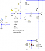
That mjr input is best for linearity, just replace BC560C with fast bjt like 2sa1206, then replace that 1k Rbe with best value when the cascode has highest gain (depend on Vbe characteristic @ Ic(mA))
If need best simplest try this one and compare the result by listening, it may better, or may not offcourse.
If need best simplest try this one and compare the result by listening, it may better, or may not offcourse.
Attachments
No. If the fourth amp was never built then the fifth is in fact the fourth. But this was never built. So the fifth was never built. Dito the sixt amp...😀The first amplifier I built...
The second amplifier I built...
The third amplifier I built...
The fourth amplifier was never built. The fifth amplifier I built (TGM5)...
The sixth amplifier I built (TGM6)...
I haven't designed my seventh amplifier yet....
Do you think I'm on the right track ?
Member
Joined 2009
Paid Member
It is a bit confusing !
That reminds me, the fourth amp (never built) had an option of Rush Cascode error amplifier - has some advantages over the LTP.
That reminds me, the fourth amp (never built) had an option of Rush Cascode error amplifier - has some advantages over the LTP.
Hi
I think the distortion created by the small signal stuff is quite insignificant even if the feedback factor is low. It is really the output stage where most of the distortion will be created along with how the previous stage drives it, and this is where the error correction will have the most effect. If the transfer for the output stage (circuit including driver stages) is linear, as far as the VAS and the appearance in the CL loop transfer, then improvement effects of error correction on the global loop will be noticeable.😉 Typically EC loops have a high bandwidth and a higher gain crossover frequency than the global loop requiring to some degree that they be shorter loops. If the EC is within the loop as a 'nested loop', then the global loop transfer has a greatly reduced amount of output stage non-linearity to deal with. I did not see an 'amplified diode' driven output stage model in your list above.
The only other type of error correction I have played with is common mode error correction, but I used this not so much for distortion correction but to modulate the bias in a bridge circuit to create a single end to balance signal converter pre-amp circuit. That's a different thread tho.🙂
Last edited:
Bigun I wonder how a singleton input would do if that singleton was to be a kulish error corrected one........
Member
Joined 2009
Paid Member
Hi CBS240,
I think you are talking about the structure of feedback here, a vast topic of course, but I am just focussing on implementation of an error amplifier. It's probably easiest to assume the scope is a simple global negative feedback amplifier in this case.
Hi Manso,
That's an interesting idea indeed - do you plan to pursue this at all ?
I was also thinking, that the series feedback at a resistive summing node is not an error amplifier by itself. Although it generates the error, it doesn't amplify and since at least one active device is required, it's possibly equivalent to a Singleton input.
Then the question becomes - is there a better error amplifier than the Singleton - perhaps it is a Kulish cell ?
If only I had the time, I tried kulish on LTP and it did improve linearity, I see no reason why it wont do the same for a singleton. The problem with singleton is linearity at high frequency compared with LTP, I think with kulish it might be as linear as LTP with the benefit of being much faster.
Ill get around to it sometime.
Ill get around to it sometime.
Hi Bigun,
I have the feeling that the explicit isolation of an 'error amp' makes things needlessly complex.
Think of an amp as a black box with two input terminal, which amplifies whatever it sees between those terminals and put the result on the output terminal.
The open loop gain and phase transfer function determine the relationship between whatever is on those inputs, and the output.
In a sense, the whole amp is the 'error amp', and how well it does depends on all stages and parts in the amp, not just the devices connected to those input pins.
For instance, improving the input stage may make the error smaller, but so does improving the Vas or the output stage.
jan
Member
Joined 2009
Paid Member
Hi Jan,
Good to hear from some of the big fish around here 🙂
Well, my thought was that there are indeed many things in the amplifier we have to get right and there might be some benefit if breaking down the problem, so to speak, and looking at one piece of it. The error amplifier being a very key piece.
Good to hear from some of the big fish around here 🙂
Well, my thought was that there are indeed many things in the amplifier we have to get right and there might be some benefit if breaking down the problem, so to speak, and looking at one piece of it. The error amplifier being a very key piece.
How big was the slew-rate of the amplifiers you built. Were they all the same? Was the output stage allways the same?
Last edited:
Member
Joined 2009
Paid Member
The output stages were all BJT emitter follower. TGM1 & 2 were the same except for LTP versus CFP LTP. TGM3 was slightly different in that the drivers were CFP rather than EF, but the output was EF and the VAS was the same. Power supplies were the same. TGM5 was CFP driving EF again. TGM6 was EF (Darlington). All used BJT Vas and bootstrapped except the symmetrical design. Mind you, I'm not suggesting the sound is all related to differences in the error amplifier although I can see that my comments might have been interpreted as such. I never did calculate or measure the slew rate - in fact I didn't consider it as much of a priority at all so you raise an interesting question, perhaps something for me to think about.
The error signal has a wider spectrum than the input signal (depending on the output stage) and the error amp (the VAS being part of it) must be able to amplify these harmonics. If not, the higher harmonics produced by the output stage cannot be compensated trough NFB. In fact, NFB cannot fully compensate the errors of an amplifier.
Member
Joined 2009
Paid Member
Hi Franz, I believe that usually the bandwidth is limited by the compensation not by the error amplifier - so all of the options for error amplifier I mentioned should be good, but those that don't require large Cdom are best
Member
Joined 2009
Paid Member
No, it was dual Singleton, cascoded - like Lazy Cat's SSA. As far as I can see, it requires a lot of matching between the two halves. I've read that such matching is best achieved with monolithic die - in my TGM5 the input pair were a single package SMD part. At some point it begs the question why not use a state-of-the-art opamp for the error amplifier, but that produces a rash and hysteria in many.
Last edited:
Barrie Gilbert's innovation worth a shot?
This is a refreshing approach to amplifier design - kudos. I too have found LTPs suck as input stages. They do seem to improve with degeneration.
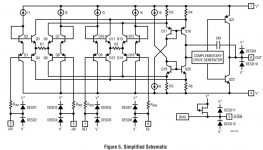
Have you tried listening to any amps based on Barrie Gilbert's AFA? They're my current favourites subjectively. So far I've only found one schematic which shows the input stage of a current design, that's in the DS for the LT6552. Here's what it looks like. Note there are two matched error amps, not one.
This is a refreshing approach to amplifier design - kudos. I too have found LTPs suck as input stages. They do seem to improve with degeneration.
Have you tried listening to any amps based on Barrie Gilbert's AFA? They're my current favourites subjectively. So far I've only found one schematic which shows the input stage of a current design, that's in the DS for the LT6552. Here's what it looks like. Note there are two matched error amps, not one.
Attachments
I can't pretend to understand the operation of post17, but to me R1 makes that effectively an LTP style input stage.
There is a significant difference - the T in an LTP is a single current source, serving both transistors. Here it is absent.
- Status
- Not open for further replies.
- Home
- Amplifiers
- Solid State
- Choosing a Feedback error amplifier